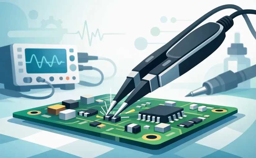
A 0402 capacitor can stop a board from starting, yet it is often the hardest part to test with ordinary meter leads. SMD test tweezers address that access problem directly: two fine, insulated probes hold the component terminals while the instrument identifies and measures the part. For PCB repair, production inspection, and prototype debugging, that changes component testing from a slow lead-placement task into a controlled two-point measurement.
What SMD Test Tweezers Measure
SMD test tweezers are handheld LCR instruments built around tweezer-shaped probes. The tips contact opposite ends of a surface-mount component, and the instrument applies an AC or DC test signal to determine electrical behavior. Depending on the model and selected mode, the result may include resistance, capacitance, inductance, impedance, ESR, DC voltage, diode characteristics, continuity, or frequency.
Their main advantage is not simply compact size. It is direct access. Standard multimeter probes can be too large for 0603, 0402, and smaller packages, and their flexible leads introduce movement that makes repeated contact difficult. Fine tweezers let the operator approach the component from above, stabilize both contacts at once, and read a result without a separate fixture.
For resistors, automatic identification is usually fast and straightforward. Capacitors and inductors require more consideration because measured values depend on test frequency, device losses, and the surrounding circuit. A professional LCR tweezer should therefore provide appropriate frequency options, stable test conditions, and accuracy specifications that are meaningful at the values being measured.
Why Test Frequency Matters on Small Components
An SMD component does not behave identically at every frequency. This is particularly relevant when testing capacitors, inductors, ferrites, and low-resistance components used in switching power supplies, RF sections, and high-speed digital designs.
A capacitor measured at a low test frequency may show a value that is acceptable for general verification but less representative of its intended operating behavior. Likewise, an inductor or ferrite bead evaluated only at a low frequency can conceal the impedance characteristics that matter in its application. Instruments with 100 kHz or 250 kHz test frequencies provide a more useful measurement range for many modern components than basic low-frequency meters.
Frequency alone does not guarantee a correct diagnosis. The selected frequency must match the measurement objective. A technician checking whether a bypass capacitor is shorted may need a quick in-circuit capacitance or resistance comparison. An engineer qualifying a small inductor for a design may need inductance, impedance, Q, or dissipation factor at a specified frequency. The appropriate tool and settings depend on the question being asked.
In-Circuit Measurement Requires Judgment
The convenience of SMD test tweezers is most apparent on populated boards, but in-circuit readings must be interpreted carefully. Parallel paths, semiconductor junctions, adjacent capacitors, and IC inputs can influence the result. A component that reads incorrectly in circuit is not automatically defective.
A low-value resistor may appear lower because of a parallel resistor or copper path. A capacitor can read higher than expected when other capacitors share the same power rail. A diode measurement can be affected by protection networks and connected transistor junctions. These effects are normal consequences of measuring a component that remains connected to a larger circuit.
The most effective approach is comparative. Measure the suspected component, then compare it with the same reference location on a known-good board or with similar components in the same circuit section. Check readings in both probe orientations when semiconductors are involved. If the in-circuit result remains ambiguous, lift one terminal or remove the component for confirmation.
This workflow avoids unnecessary rework. Removing a small multilayer ceramic capacitor or fine-pitch resistor before establishing evidence can damage pads, disturb neighboring parts, and consume more time than the original fault warrants.
Selecting SMD Test Tweezers for the Job
The right instrument depends on component types, required accuracy, and whether measurements must be documented. Basic models can be effective for general resistor, capacitor, and diode checking. Repair labs and engineering groups working on tighter tolerances should evaluate basic accuracy, available test frequencies, repeatability, calibration support, and probe-tip options.
For example, 0.1% or 0.2% basic accuracy has practical value when sorting precision resistors, verifying low-tolerance components, or comparing changes across a production run. It is less decisive when locating a clearly shorted 10 uF rail capacitor. Accuracy should be evaluated alongside resolution, measurement range, and performance at the actual impedance and frequency of interest.
Probe geometry also matters. Fine gold-plated tips can access dense layouts, but tips that are too sharp may slip between pads or mark soft component terminations if used carelessly. Replaceable tips are useful in service environments where repeated contact eventually causes wear. Proper insulation near the tips reduces the risk of bridging adjacent pads, especially around fine-pitch ICs and tightly packed passives.
Calibration is another differentiator for professional use. A NIST-traceable calibration certificate supports quality systems, incoming inspection requirements, and documented measurement practices. For an occasional bench tool, that may not be a purchasing priority. For a production, service, or quality-control environment, it can be essential.
A Practical PCB Troubleshooting Sequence
Start with power removed unless the measurement specifically requires a live circuit. Inspect the board first for cracked capacitors, overheated resistors, corrosion, solder bridges, and missing components. Visual inspection often identifies the area that deserves measurement before any instrument is applied.
Next, verify the obvious faults. Use resistance or continuity measurements to locate shorted power rails, then compare capacitors along the affected rail. A very low reading on one capacitor relative to nearby parts may identify the likely fault location. When checking resistors, compare the displayed value with the marking, schematic, bill of materials, or a matching channel on the board.
For a suspected diode, LED, or transistor junction, use the instrument’s appropriate semiconductor test function and reverse probe orientation where applicable. A forward drop, open reading, or low resistance in both directions can provide useful evidence, but circuit context still matters. Connected IC pins and protection diodes may produce readings that resemble a component fault.
Finally, record results when the work requires traceability. Bluetooth-enabled models can improve this part of the workflow by transferring readings to a mobile device or PC rather than relying on handwritten notes. That is particularly useful during recurring repair, incoming inspection, failure analysis, or when an engineer needs to share measured data with a remote team.
Beyond Basic LCR Measurements
Some faults cannot be confirmed by a single capacitance or resistance value. Intermittent behavior, damaged semiconductor structures, and partially failed passive parts may require a broader view of the circuit. Advanced handheld instruments can combine LCR measurement with oscilloscope capability or Analog Signature Analysis to help identify abnormal component behavior.
Analog Signature Analysis is valuable when comparing an unpowered suspect circuit against a known-good section or board. Instead of relying only on a numeric reading, the technician examines the voltage-current signature created by the test signal. A changed curve can reveal a leakage path, open junction, or altered component behavior that a basic meter reading may not make obvious.
That capability does not replace conventional measurements. It complements them. Numeric LCR results are efficient for identifying nominal values and verifying tolerances, while signature-based comparison can help when the circuit connection makes a simple in-circuit result uncertain.
Getting Repeatable Readings
Good technique has a direct effect on measurement stability. Clean the probe tips, hold the instrument so both tips contact the terminal surfaces rather than solder-mask edges, and avoid pressing hard enough to move the component. Allow the reading to settle before recording it, especially when measuring higher-value capacitors or inductive parts.
Zeroing or calibration compensation should be performed according to the instrument procedure, particularly after changing tips. Keep the tips clean and aligned, and use an appropriate accessory or external probes when the component location cannot be safely reached with the integrated tweezers. A compact instrument is only as effective as the contact it makes.
Siborg Systems Smart Tweezers and LCR-Reader instruments are designed around this direct-contact workflow, with configurations ranging from portable component identification to advanced high-frequency and Bluetooth-enabled measurement. The practical value is simple: less time fighting probe placement, more time determining what the component and circuit are actually doing.
When a board fault comes down to one part among hundreds, the best measurement tool is the one that gives you stable contact, relevant test conditions, and enough confidence to make the next repair decision without removing components prematurely.