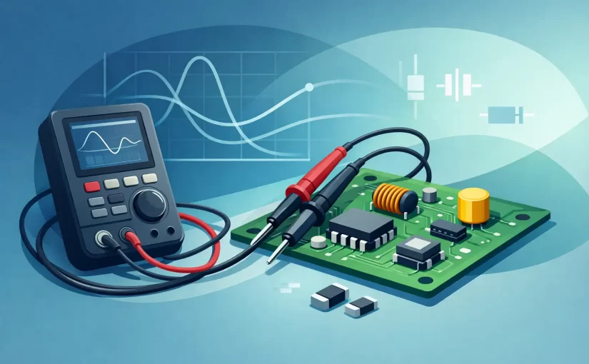
A 250 kHz LCR meter is not simply a faster version of a standard bench LCR meter. Its value is that it tests components closer to the operating conditions where many small SMD parts, switching-power components, and high-frequency networks reveal their real behavior. For PCB repair, incoming inspection, and component verification, that additional test frequency can separate a plausible reading from a useful diagnosis.
A resistor that appears correct at a low test frequency may be easy to confirm with a multimeter. A small capacitor or inductor is different. Parasitic resistance, lead and fixture effects, dielectric behavior, and PCB coupling become increasingly significant as frequency rises. A meter capable of 250 kHz gives technicians and engineers another measurement point when a 1 kHz or 10 kHz result does not explain circuit performance.
Why 250 kHz Changes LCR Measurement
LCR instruments apply an AC test signal and calculate component parameters from the response. Depending on the selected measurement mode, the display may show inductance, capacitance, resistance, impedance, ESR, dissipation factor, or quality factor. The selected frequency matters because the device under test is not an ideal component.
At low frequencies, a capacitor may look primarily capacitive and an inductor primarily inductive. At higher frequencies, equivalent series resistance and parasitic inductance or capacitance influence the result. This is especially relevant for compact multilayer ceramic capacitors, small RF inductors, ferrite beads, chip coils, and components installed around switching regulators.
A 250 kHz test frequency is useful because it sits well above the frequencies offered by many general-purpose handheld meters. It can provide a more discriminating view of low-value components without requiring a full impedance analyzer for routine service work. It does not replace characterization across a broad frequency sweep, but it is an efficient frequency for finding parts that have drifted, become lossy, or no longer match neighboring devices.
The measurement is still application-dependent
Higher frequency is not automatically the correct setting. A large electrolytic capacitor may be specified or evaluated at 100 Hz, 120 Hz, or 1 kHz, while a precision film resistor may need a low-stress measurement setup to achieve its rated tolerance. The best test frequency depends on the component type, value, circuit function, and the specification being checked.
The practical advantage of a multi-frequency instrument is choice. A technician can compare readings at 1 kHz, 10 kHz, 100 kHz, and 250 kHz when the instrument supports those ranges, then determine whether the component behaves consistently or changes in a way that warrants closer investigation.
Where a 250 kHz LCR Meter Is Most Useful
Small inductors are one of the clearest use cases. In power-management circuits, inductors and ferrite components may pass a basic continuity check while their inductance, series resistance, or frequency response is no longer suitable for the converter. Measuring at 250 kHz can help expose a questionable part in circuits that switch in or near that region.
High-frequency ceramic capacitors are another strong candidate. Their effective capacitance changes with DC bias, temperature, package size, and frequency. An in-circuit reading must be interpreted carefully, but comparing matching capacitors in identical circuit locations can quickly identify an outlier. A 250 kHz reading can be more meaningful than a low-frequency capacitance value when the capacitor is part of a fast bypass, timing, or filtering network.
RF and communications boards also benefit from higher-frequency LCR testing. Chip inductors, small capacitors, and impedance-matching components are sensitive to placement and parasitics. A portable meter will not replace a vector network analyzer for RF design validation. It can, however, provide rapid component-level screening during assembly inspection, repair, and fault isolation.
For manufacturing and quality control, 250 kHz measurement supports comparison against approved samples. The goal is often not to fully model a component. It is to confirm that a reel, assembled board, or replacement part behaves within an expected range at a relevant test condition. Repeatable fixtures, a documented test frequency, and traceable calibration make those comparisons defensible.
In-Circuit Testing Requires Judgment
Testing a component on a populated board saves time, but the meter sees the whole network connected to the test points. Parallel paths can make resistance read low, nearby capacitors can increase apparent capacitance, and semiconductor junctions can affect the result. At 250 kHz, trace inductance and coupling between nearby circuit elements can add further error.
That does not make in-circuit testing ineffective. It changes the method. Use the reading to compare like-for-like locations, known-good boards, or components of the same design. If a value is questionable, isolate one terminal or remove the component before making a final disposition. This approach is faster than desoldering every suspected part and more reliable than accepting one isolated meter reading as proof.
Contact quality is equally important. Standard test leads are often too large and too unstable for 0402, 0201, and other small SMD packages. Spring-loaded tweezer probes provide direct access to both component terminals, reduce hand movement, and make it easier to repeat a measurement. Short test paths also reduce the fixture inductance and capacitance that become more relevant at high frequency.
Before measuring low impedance or small capacitance, perform open and short compensation using the intended probes or tweezers. Compensation removes a portion of the fixture contribution, but it cannot correct poor contact, dirty terminals, or a component surrounded by an active circuit network. Keep the board unpowered and discharge capacitors before connecting the meter.
Specifications That Matter Beyond 250 kHz
Test frequency is only one part of instrument selection. Basic accuracy determines how closely a reading can approach the actual value under stated conditions. For component sorting, production inspection, and engineering records, 0.1% or 0.2% basic accuracy may matter as much as the frequency range. Review accuracy at the range and test frequency you intend to use, rather than relying on a single headline specification.
Resolution also deserves attention. A meter may support 250 kHz yet not provide enough stable resolution for the low-value capacitor or inductor being tested. Look at the minimum measurable value, display digits, measurement speed, and the behavior of the auto-ranging system. A fast reading is useful only if it settles consistently.
Measurement modes should match the work. Series and parallel equivalent models are not interchangeable. Series mode is generally appropriate when ESR is a significant part of the component behavior, while parallel mode is often useful for high-impedance components. The correct choice depends on the component and test conditions. An instrument that clearly provides L, C, R, ESR, D, Q, and impedance data gives the operator more context than one that displays a single nominal value.
Calibration documentation matters in professional environments. A NIST Traceable Calibration Certificate supports quality-system requirements and gives confidence that the meter has been checked against recognized standards. Field users should also consider probe wear, battery condition, mechanical durability, and whether calibration intervals fit their operating procedures.
Handheld Tweezers Versus Conventional Fixtures
Conventional LCR meters with test leads and Kelvin fixtures remain appropriate for many lab measurements. They can offer controlled connections and are well suited to larger through-hole components or dedicated production fixtures. Their limitation is speed when the work involves dense boards and tiny parts.
Tweezer-style LCR meters address that workflow directly. The probe and measurement interface are combined, allowing the user to grip an SMD component, read the value, and move to the next location with minimal setup. For repair benches, rework stations, and incoming inspection, this can reduce handling time substantially.
Siborg Systems instruments such as the Smart Tweezers and LCR-Reader families combine this direct-contact approach with high-frequency measurement options, including models rated to 250 kHz. Advanced configurations may also add Bluetooth data transfer, oscilloscope functions, or Analog Signature Analysis for technicians who need more than an LCR value during board-level troubleshooting.
A Practical 250 kHz Measurement Workflow
Start by identifying what the component should do in the circuit. A 10 nF bypass capacitor, a 2.2 µH converter inductor, and a ferrite bead should not be evaluated using the same expectation or parameter. Select the closest relevant frequency, then compare the result against the component datasheet, a known-good board, or an identical location.
Use short, clean probes and compensate the instrument before testing. Make contact squarely on the component terminals without pressing hard enough to damage a small package or lift a weak pad. If readings shift significantly when the probes move, improve contact before judging the component.
When a reading is surprising, check it at more than one frequency. A stable component usually changes in a pattern that makes electrical sense. A reading that is unstable, inconsistent with adjacent matching parts, or dramatically different at 250 kHz may indicate damage, a parallel circuit path, or an unsuitable in-circuit test condition. Isolate the part only when the evidence justifies the extra rework.
The most productive use of a 250 kHz LCR meter is not to measure every component at the highest available frequency. It is to apply the frequency where it adds diagnostic separation, document repeatable results, and turn a compact measurement into a confident repair or inspection decision.