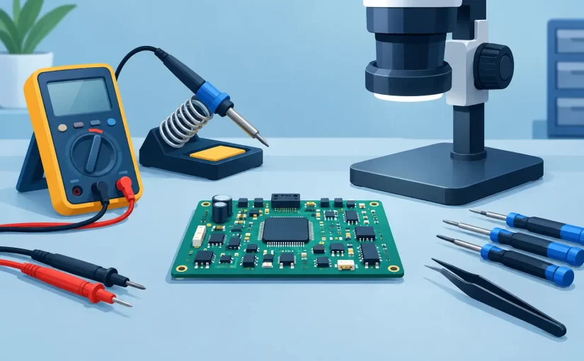
A board can look perfect under magnification and still fail because of one 0402 capacitor, a damaged MLCC, or an inductor that has shifted outside its working range. Effective electronics repair tools shorten the path from symptom to component-level evidence. For PCB diagnosis, tool selection is less about owning the largest collection and more about making reliable measurements quickly, safely, and at the frequencies that matter.
Electronics Repair Tools Start With the Measurement Task
A digital multimeter remains the first instrument most technicians reach for. It is appropriate for confirming supply rails, continuity, diode junction behavior, DC resistance, current draw, and basic voltage references. It is not, however, a complete component analyzer. A multimeter may indicate that a capacitor is not shorted while providing no useful indication of its capacitance, ESR, dissipation factor, or behavior at a relevant test frequency.
That distinction matters on densely populated boards. Switching power supplies, RF sections, display drivers, battery-management circuits, and high-speed digital assemblies often depend on small passive components whose faults are not visible through DC checks alone. An LCR meter or ESR meter adds the measurements needed to assess resistors, capacitors, and inductors as components rather than simply as conductive paths.
The correct instrument depends on the failure mode being investigated. If a rail is absent, start with voltage and continuity. If the rail is present but unstable, evaluate the capacitors and inductors supporting that circuit. If a signal path is distorted or intermittent, waveform inspection and analog signature comparison can identify differences between a known-good and suspect section. Good troubleshooting follows the circuit, rather than forcing every question through one meter.
Accuracy Is Only Useful at the Right Frequency
Basic accuracy is a meaningful specification, but it should not be considered in isolation. A 0.1% or 0.2% basic accuracy specification supports confident comparison and verification when the test conditions match the component and application. Test frequency is equally important, particularly for capacitors and inductors.
A capacitor measured at a low frequency can appear acceptable while exhibiting excessive loss or impedance under the operating conditions of a switching circuit. Likewise, inductance readings can vary with frequency, DC bias, core material, and the component’s connection to the surrounding circuit. Instruments with 100 kHz or 250 kHz test capability provide more useful characterization for many modern PCB applications than meters limited to low-frequency measurement.
In-circuit readings still require judgment. Parallel components, semiconductor junctions, control ICs, and alternate current paths can influence the result. A reading that differs from the marking or schematic is not automatically proof of a defective part. Compare equivalent locations where possible, isolate one end of the component when the diagnosis requires certainty, and account for the circuit topology before ordering a replacement.
Direct Access Matters More Than Lead Length
Conventional probe leads are flexible and familiar, but they become inefficient on boards populated with 0201, 0402, and 0603 components. The technician must stabilize the board, place two probes on tiny terminations, avoid bridging adjacent pads, and keep the test contact consistent long enough for the reading to settle. That process is slow, especially during repetitive inspection or production rework.
Tweezer-style LCR instruments address this access problem directly. Insulated tips provide two-point contact at the component terminals, allowing the operator to pick up loose SMD parts or measure accessible devices on the board. The mechanical design is not a convenience feature alone. It improves repeatability by reducing hand movement and making the contact geometry more consistent from measurement to measurement.
For repair work, tip selection also affects results. Fine tips improve access between tightly spaced parts but can be easier to damage. Wider or more durable tips can be better for frequent work on larger passives. Replaceable probing accessories allow one instrument to adapt to bench diagnosis, field service, loose-component verification, and populated-board inspection without compromising the primary measurement method.
Siborg Systems instruments such as Smart Tweezers and LCR-Reader models are designed around this direct-contact workflow, combining handheld SMD access with professional LCR measurement capabilities. The relevant configuration depends on whether the priority is entry-level identification, higher test frequencies, Bluetooth data transfer, or expanded diagnostic functions.
Build a Bench Around Complementary Functions
A capable repair bench does not need duplicate instruments. It needs coverage across the measurements that separate common faults. Start with a quality digital multimeter for electrical safety checks and DC diagnosis, then add specialized tools where they remove uncertainty.
An LCR meter is the primary addition for passive-component work. Look for clear measurement of capacitance, resistance, inductance, ESR, dissipation factor, and impedance, along with selectable test conditions where applicable. Automatic component identification is valuable when sorting unknown loose parts, but manual mode remains important when a specific parameter and frequency are required.
An ESR meter is particularly useful when evaluating capacitors in power circuits. High ESR can cause ripple, poor regulation, startup failure, heat, or intermittent operation even when nominal capacitance appears close to specification. This is especially relevant for electrolytic capacitors, but low-ESR ceramic and polymer capacitors also require measurement conditions appropriate to their application.
Oscilloscope capability belongs on the bench when a fault involves timing, ripple, switching activity, serial communications, or intermittent signal behavior. For compact field work, integrated oscilloscope functions can provide a fast first view. A dedicated bench oscilloscope remains preferable when bandwidth, multiple channels, triggering depth, or detailed waveform analysis is required. The trade-off is straightforward: integrated functions improve portability, while separate instruments provide broader analysis capacity.
Analog Signature Analysis adds another comparison method. By applying an AC stimulus and observing the resulting current-voltage signature, a technician can compare devices or circuit nodes without powering the board. It is not a replacement for LCR measurement or a scope, but it can help locate shorts, opens, leakage paths, and abnormal semiconductor behavior when a known-good comparison point exists.
Protect the Board and the Measurement
Precision instruments cannot compensate for poor probing practice. Before measuring a board, verify the power state, identify energy-storage capacitors, and discharge circuits where necessary. An ESR or LCR measurement performed on a charged capacitor can damage the instrument, the board, or both.
ESD control is equally practical. Use a grounded work surface and wrist strap when handling static-sensitive assemblies, particularly boards containing CMOS logic, RF front ends, memory devices, and fine-pitch controllers. Keep probe tips clean and inspect them for bent points, worn insulation, or contamination that can cause unstable contact.
When troubleshooting powered circuits, choose probes and accessories rated for the voltage and environment involved. Keep one hand clear of the assembly where appropriate, secure the board so it cannot shift, and avoid relying on improvised metal tools near exposed conductors. Fast diagnosis is valuable only when it does not introduce a second fault.
Make Results Repeatable and Defensible
Repair decisions often move beyond the individual technician. Manufacturing teams may need incoming inspection records. Service organizations may need proof of a completed repair. Engineering groups may need to compare a returned board against reference data. In these cases, repeatability and documentation are part of the tool requirement.
Calibration support is one consideration. A NIST Traceable Calibration Certificate provides documented confidence that an instrument has been verified against recognized standards. It does not eliminate the need for careful operation, open and short compensation, or routine inspection of probes and tips. It does provide a traceable basis for measurements used in quality systems, customer reports, and controlled repair processes.
Bluetooth-enabled instruments can further improve workflow when measurements must be captured instead of transcribed. Recording values to a mobile device or PC reduces transcription errors, supports comparison over time, and creates a clearer service record. Wireless transfer is most useful when it fits an established process. For a single loose component, reading the display may be faster. For batch inspection or recurring failure analysis, captured data becomes a practical advantage.
Choose Tools for the Work You Actually Perform
A technician repairing consumer electronics may prioritize portability, SMD access, capacitance, ESR, and diode testing. A manufacturing quality team may place more weight on accuracy, calibration documentation, repeatable fixtures, and data capture. An engineer working with power electronics may require higher-frequency LCR measurement, waveform visibility, and accessories that tolerate larger components and higher-energy environments.
Avoid selecting tools solely by the longest feature list. A high-frequency LCR meter is valuable when the application calls for it, but it may be unnecessary for occasional through-hole repair. Bluetooth is useful when measurements need to be retained, not simply because it is available. The best electronics repair tools are the ones that reduce uncertainty at the exact point where your current workflow slows down.
Keep the bench organized around that principle. Measure the circuit state first, test passive components under meaningful conditions, use direct-contact probes where board density demands them, and document results when the repair must be repeatable. A technician who can trust the measurement can make the next decision with speed rather than guesswork.