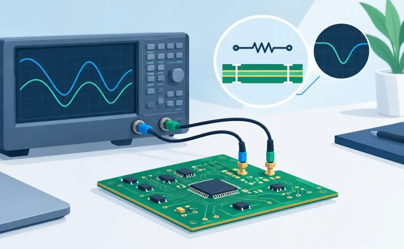
A 10 uF ceramic capacitor can appear healthy at 1 kHz and become the source of a power-rail problem at a higher operating frequency. A resistor can measure correctly in DC resistance mode while its parasitic inductance affects a high-speed circuit. This impedance measurement guide focuses on obtaining readings that represent component behavior under real test conditions, not merely a number displayed by an instrument.
What impedance measurement actually measures
Impedance is the opposition a component or network presents to alternating current. It includes resistance and reactance, so it is expressed as a complex quantity with magnitude and phase. Resistance dissipates energy. Capacitance and inductance store and release energy, producing reactance that changes with frequency.
For a resistor, impedance may remain close to its stated resistance over a useful frequency range. For a capacitor, capacitive reactance decreases as frequency rises. For an inductor, inductive reactance increases with frequency. Real components also contain parasitic resistance, inductance, and capacitance, which eventually dominate the result.
That distinction matters during PCB diagnosis. Measuring only DC resistance cannot show capacitor ESR, inductor loss, resonance, or the frequency-dependent loading caused by a component package and its board layout. An LCR meter applies an AC test signal, measures voltage and current, and calculates the selected equivalent parameters at a defined test frequency.
Select the frequency before interpreting the value
A valid impedance reading begins with a relevant frequency. Component data sheets commonly specify capacitance, inductance, dissipation factor, Q, or ESR at a stated frequency and test level. Measuring at a different condition is not necessarily wrong, but it answers a different question.
For general component identification, 100 Hz, 1 kHz, or 10 kHz can be appropriate starting points. Higher frequencies are more useful when evaluating low-value capacitors, small inductors, RF-adjacent circuits, switching power supplies, and the parasitic behavior of SMD components. A 100 kHz or 250 kHz measurement capability can reveal behavior that is hidden at audio-range test frequencies.
The correct choice depends on the fault and the component. A bulk electrolytic capacitor in a low-frequency filter may be assessed effectively at lower frequencies, with ESR included in the evaluation. A multilayer ceramic capacitor supporting a fast digital rail should be checked closer to the frequencies where low impedance is required. Do not expect a single frequency to characterize every component.
Watch for self-resonance
Every physical capacitor and inductor has a self-resonant frequency. A capacitor behaves capacitively below resonance, reaches minimum impedance near resonance, and appears inductive above it. An inductor behaves inductively below resonance and becomes increasingly capacitive above it.
If a reading seems inconsistent with the component marking, check the test frequency before assuming the part has failed. At higher frequencies, a small change in fixture position, lead length, or PCB trace geometry can also affect the measurement.
Choose the right equivalent circuit
Most LCR instruments report component values using series or parallel equivalent circuits. This selection affects the displayed resistance, loss, Q, and dissipation factor, especially when the device under test has significant loss.
A series model represents the component as an ideal reactance in series with a resistance. It is commonly useful for low-impedance capacitors and inductors, where lead resistance, winding resistance, or ESR is naturally modeled in series. A parallel model represents an ideal reactance alongside a resistance and is often appropriate for high-impedance components and leakage-dominated behavior.
As a practical rule, use the model specified by the component manufacturer whenever possible. If no specification is available, compare the measured impedance magnitude with the instrument’s applicable model guidance. Recording only “10 nF” is incomplete when loss and frequency are relevant. Record capacitance or inductance, the selected series or parallel mode, test frequency, and the associated ESR, D, or Q value.
Establish a controlled measurement setup
The instrument, fixture, and operator form part of the measurement system. This is particularly true for milliohm-level ESR, low-inductance capacitors, and small SMD parts. Poor contact pressure or oxidation can produce an apparent component defect.
Start by allowing the meter to stabilize according to its operating instructions. Use the shortest practical test path and select probes or tweezers that match the component size. Dedicated tweezer-style contacts reduce loop area and make it possible to contact opposing SMD terminations directly, rather than chasing a small part with conventional test leads.
Perform open and short compensation with the same fixture and approximate measurement geometry used for the test. Open compensation reduces the influence of stray capacitance. Short compensation reduces residual lead resistance and inductance. Compensation is not optional housekeeping when measuring very small values. It is the reference that separates the fixture from the device under test.
For repeatable production or laboratory work, control contact location and pressure. A probe touching the end cap of a chip capacitor may not produce the same result as one contacting a nearby solder fillet, especially at higher frequencies. Use a holder, fixture, or consistent technique when measurements will be compared across operators or lots.
Measure loose parts first when possible
A loose component measurement provides the clearest indication of the part itself. Remove the component from static-sensitive packaging only with suitable ESD controls, identify its value and package, compensate the fixture, and take readings at the frequencies that match the intended application or data sheet conditions.
For loose parts, confirm more than the nominal value. A capacitor may show the correct capacitance but excessive ESR. An inductor may measure its stated inductance but have poor Q or higher-than-expected winding resistance. A resistor can pass a low-frequency resistance check while showing unexpected inductive behavior at the circuit’s operating range.
Smart Tweezers and LCR-Reader instruments are designed for this direct-contact workflow, allowing technicians to identify and measure SMD components without changing from long test leads to a separate fixture. The benefit is not just speed. Short, controlled contacts reduce the uncertainty added by loose probe wiring.
Understand the limits of in-circuit impedance tests
In-circuit testing is fast, but the reading represents every available path connected to the probes. A capacitor measured across a power rail may be in parallel with several other capacitors, integrated circuits, protection devices, and converter stages. A resistor can be shunted by another branch. An inductor can be affected by semiconductor junctions or transformer windings.
Use in-circuit impedance measurement as a diagnostic comparison tool. Compare identical channels, known-good boards, or equivalent locations on the same board. A significantly lower impedance on one rail may indicate a shorted capacitor or semiconductor. A substantially different ESR reading may identify a degraded capacitor, but confirm the result after isolating the part if parallel paths are plausible.
Power must be removed before ordinary passive-component measurement. Discharge capacitors safely and verify that stored voltage is absent. An energized board can damage the instrument, create misleading readings, or place an active circuit in an unintended state.
A practical isolation strategy is to lift one terminal only when necessary. This removes most parallel ambiguity while minimizing rework compared with complete removal. For dense assemblies, inspect the schematic or board topology first. Knowing which components share a node prevents wasted troubleshooting time.
Read ESR, D, and Q in context
ESR is especially useful for capacitors in power conversion, filtering, and decoupling roles. High ESR increases ripple voltage, heat, and losses. However, a low ESR value is not automatically good if it is inconsistent with the capacitor technology or if the measurement frequency is inappropriate.
Dissipation factor, or D, expresses loss relative to reactance. Lower D generally indicates lower loss in capacitive measurements. Quality factor, Q, is the inverse relationship used frequently for inductors and resonant components. A falling Q can point to core loss, winding loss, damage, or test conditions outside the part’s intended range.
Use the specification as the acceptance limit whenever one exists. Generic pass-fail values are unreliable because a polymer capacitor, aluminum electrolytic, MLCC, ferrite inductor, and air-core coil are designed for different impedance and loss characteristics.
Document measurements that others can use
A useful record includes the component reference designator, nominal value, measured value, test frequency, test level if available, equivalent circuit mode, fixture compensation status, and whether the test was in circuit or out of circuit. Add board revision and ambient conditions for failure analysis or quality work.
Bluetooth or PC-connected measurement tools can reduce transcription errors when many readings must be captured, compared, or attached to a service report. Digital capture is most valuable when it preserves the conditions behind the number. A spreadsheet of capacitance values without frequency, mode, and test location can be difficult to interpret later.
Accurate impedance work is a matter of matching the meter, frequency, fixture, and circuit context to the question being asked. When a result is surprising, treat it as evidence to investigate rather than an immediate verdict on the component.