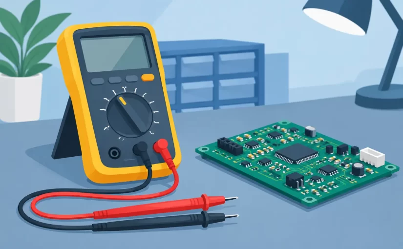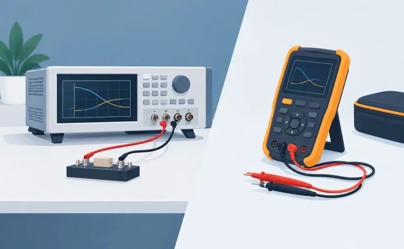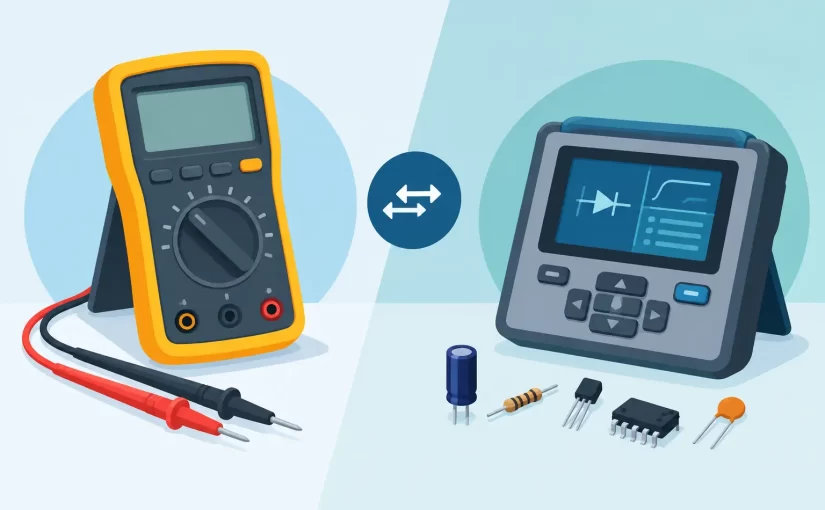
A failed board rarely presents one obvious bad part. A power rail may collapse because of a shorted ceramic capacitor, an intermittent inductor, a resistor installed with the wrong value, or a semiconductor fault elsewhere on the net. A digital component tester shortens that search by bringing direct identification and measurement to the component itself, especially where conventional probes are too large or too slow for densely populated PCB assemblies.
For engineers, repair technicians, and quality teams, the useful question is not whether an instrument can produce a reading. It is whether that reading is made at a suitable test frequency, with adequate accuracy, repeatable contact, and enough context to support a repair or production decision.
What a Digital Component Tester Should Measure
A basic component tester can identify common passive components and provide approximate values. That can be useful on loose through-hole parts, incoming inspection, or sorting mixed inventory. PCB diagnostics usually demand more. Small SMD components, parallel paths, solder flux residue, and nearby semiconductors can all affect an in-circuit measurement.
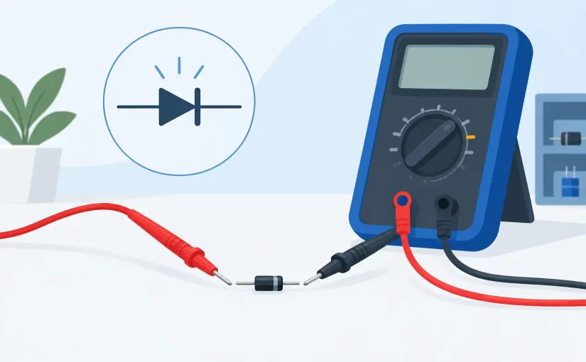
A professional digital component tester should measure resistance, capacitance, and inductance with clearly defined test conditions. ESR measurement is particularly useful when evaluating electrolytic capacitors, polymer capacitors, and other parts whose capacitance may appear acceptable while their loss characteristics have changed. Diode and transistor functions can help with initial semiconductor checks, although they do not replace application-specific circuit analysis.
Test frequency matters because component behavior changes with frequency. An inductor measured at a low frequency can appear satisfactory but behave differently in a switching circuit. Capacitors also have frequency-dependent impedance and dissipation characteristics. Instruments offering 100 kHz or 250 kHz test capability provide a more relevant view for many high-frequency, switching-power, RF-adjacent, and compact digital designs than low-frequency-only measurements.
Accuracy should be evaluated beyond the headline specification. Basic accuracy of 0.1% or 0.2% is valuable, but real measurement confidence also depends on probe condition, contact resistance, calibration status, component range, and the selected measurement mode. An instrument should state its accuracy, test signal, frequency, and measurement range clearly enough for the user to judge whether it fits the task.
Why Tweezer-Style Probing Changes PCB Work
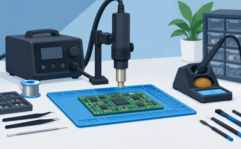
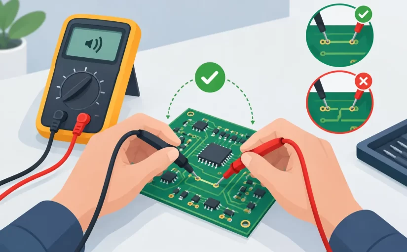
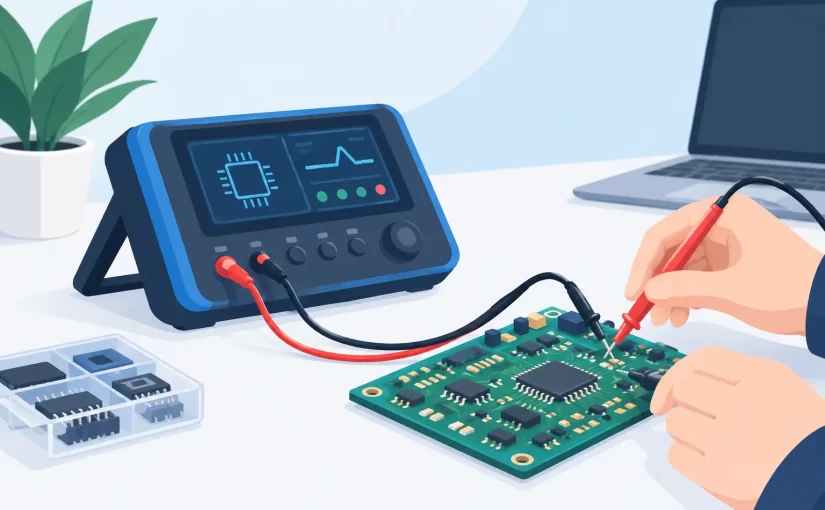
The limiting factor in component testing is often not the measurement engine. It is physical access. Standard multimeter leads can bridge adjacent pads, slip off 0402 or 0201 packages, or require a third hand to hold the board and probes in place. Fine test tweezers place both measurement contacts at the component terminals in one motion.
This approach improves speed, but its greater value is consistency. The same controlled contact pressure and short probe path can reduce the variable introduced by loose leads and improvised clips. On crowded boards, a technician can isolate a chip resistor, capacitor, or inductor without placing two large probe tips across neighboring circuitry.
For loose SMD parts, tweezers also reduce handling time. A technician can pick up a component, measure it, and place it in a labeled tray without changing tools. For production inspection and rework verification, that repeated workflow is more efficient than using separate probes for every part.
Siborg Systems’ Smart Tweezers instruments are designed around this direct-contact method, combining tweezer-style probing with LCR measurement for loose and in-circuit component work. The configuration is especially practical when the board layout, rather than the component specification, is the primary obstacle.
In-Circuit Readings Require Judgment
No digital component tester can fully separate a component from every circuit path while it remains soldered to a board. A resistor may be shunted by another resistor or an IC input. A capacitor may be effectively paralleled by several capacitors on the same supply rail. An inductor may share a path through a switching controller, diode, or transformer winding.
The correct approach is to treat an in-circuit result as diagnostic evidence, not automatic proof. If a 10-ohm resistor reads 2 ohms in circuit, the reading may indicate a failed resistor, but it may also show a legitimate parallel load. Compare with a known-good board where possible. Check the schematic, boardview data, or neighboring channels. If the result remains questionable, lift one terminal and remeasure the part out of circuit.
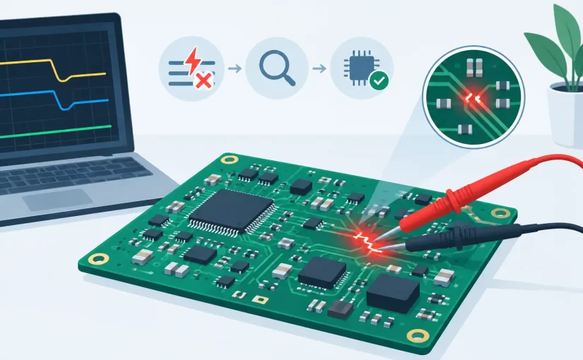
Capacitor troubleshooting illustrates this distinction well. A low-resistance rail-to-ground reading can identify a shorted area quickly, but a component tester alone may not identify which capacitor is defective when many are in parallel. The tester is strongest when used with a structured workflow: locate the abnormal net, identify candidate components, compare measurements, and confirm by isolation when needed.
Selecting the Right Measurement Capabilities
Instrument selection should begin with the boards and components being serviced. A technician repairing consumer power supplies has different priorities from an engineer validating RF matching networks or a manufacturer checking SMD reels.
For general PCB repair, resistance, capacitance, inductance, diode testing, and ESR provide a solid starting point. For switching supplies and modern compact electronics, higher test frequency and reliable low-value measurement become more significant. Low inductance, low resistance, and small ceramic capacitors are common precisely where poor probes and limited frequency capability can produce misleading results.
Consider these operational requirements before selecting a tester:
- Basic accuracy and resolution: Determine whether the instrument can distinguish the tolerances and fault levels relevant to the components under test.
- Available test frequencies: Higher-frequency LCR testing can better represent components used in switching and high-speed circuits.
- In-circuit usability: Fine probes or tweezers should reach small packages without contacting adjacent pads.
- Calibration documentation: NIST-traceable calibration certificates support quality systems, formal labs, and measurement records.
- Data capture: Bluetooth or PC-connected capability is useful when readings must be logged, reviewed, or transferred to a report.
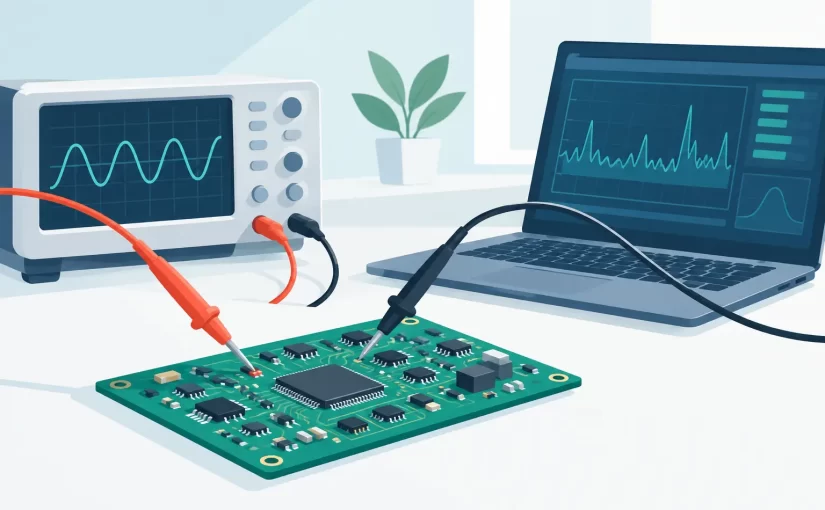
- Advanced diagnostic functions: Oscilloscope and Analog Signature Analysis modes can add fault-isolation options beyond passive component measurement.
Not every user needs every function. A bench technician sorting components may place the highest value on speed and automatic identification. A field service specialist may prioritize portability, battery operation, and repeatable in-circuit access. An engineering lab may need traceable calibration, high-frequency testing, and digital records. Buying for the actual workflow is more useful than comparing a single specification in isolation.
A Practical PCB Diagnostic Sequence
Begin with visual inspection. Look for cracked MLCCs, discolored resistors, lifted pads, corrosion, damaged connectors, and heat-stressed electrolytics. A tester cannot compensate for a missed physical defect.
Next, power down the board and discharge capacitors as required. Measuring a charged capacitor or energized circuit risks damaging both the instrument and the board. Check suspect power rails for an abnormal resistance-to-ground condition, then use the component tester to compare nearby components and identify values that differ from equivalent locations.
When measuring a passive component, let the instrument settle before recording the result. Clean oxidized terminals when practical, and verify that tweezer tips are properly aligned and free of contamination. If the reading changes noticeably with probe pressure or position, contact quality may be the problem rather than the part.
For board-level faults that remain ambiguous, add other methods rather than forcing a conclusion from one measurement. A thermal camera, controlled current injection, oscilloscope trace, or Analog Signature Analysis comparison can reveal behavior that static LCR testing cannot. Effective troubleshooting is a sequence of increasingly specific evidence, not a single test.
Protecting Measurement Confidence Over Time
A precision instrument remains useful only when its probes, calibration, and handling are maintained. Fine tweezer tips are wear items. Bent, contaminated, or heavily oxidized tips can raise contact resistance and create unstable readings, particularly on low-ohm components and small pads. Replace or service accessories before they become a source of uncertainty.
Calibration is equally practical, not merely administrative. For organizations documenting repair quality or validating production measurements, a current NIST-traceable calibration certificate provides a defensible reference point. Even for independent technicians, periodic verification against known standards helps identify drift or damaged probes before a questionable measurement reaches a customer report.
A digital component tester earns its place on the bench when it reduces uncertainty at the exact point where troubleshooting slows down: the individual part on a crowded PCB. Select measurement frequency, accuracy, probing method, and documentation capabilities for the boards you actually service, then use the instrument as part of a disciplined diagnostic process. The result is not just a faster reading, but a better-supported decision about what to repair, replace, or investigate next.