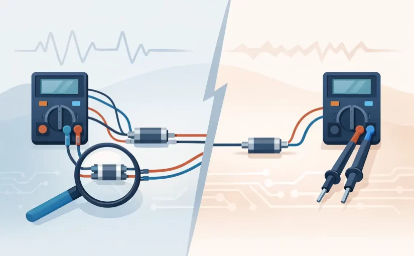
A 0.050 ohm resistor, a relay contact, or a short PCB trace can be electrically sound while appearing out of tolerance on a two-wire meter. The reason is usually not the component. It is the measurement path. In four wire versus two wire resistance measurement, the practical difference is whether test-lead, probe-contact, and fixture resistance become part of the displayed result.
For general-purpose resistance work, two wires are fast and adequate. For milliohm-level values, low-resistance interconnects, production fixtures, and precision current-sense components, four-wire Kelvin measurement removes a major source of uncertainty. Selecting the correct method starts with knowing what the instrument is actually measuring.
What a Two-Wire Measurement Includes
A two-wire resistance measurement uses the same pair of leads to force test current through the device under test and measure the resulting voltage. The meter calculates resistance from Ohm’s law: R = V/I.
This arrangement is simple, portable, and appropriate for a wide range of work. It is the normal method for checking a 10 kOhm resistor, confirming an open fuse, measuring a thermistor, or sorting common discrete components. When the device resistance is large relative to the resistance of the probes and their contacts, the added error is insignificant.
The limitation becomes clear at low values. A two-wire reading includes resistance from both leads, probe tips, oxide films, connector interfaces, clips, solder joints, and any fixture contacts in series with the component. If the test leads and contacts contribute 0.18 ohm, measuring a 0.10 ohm part may produce a reading near 0.28 ohm. A meter with excellent basic accuracy cannot mathematically remove resistance it has been instructed to include.
A relative or zero function can reduce the effect of stable lead resistance. Short the probes together, store the offset, and measure the part. This is useful for quick work, but it has limits. Probe pressure changes, contamination, movement, and different contact points can alter the resistance after the zero operation. Relative mode is not a substitute for a true Kelvin connection when repeatability matters.
Four Wire Versus Two Wire: The Kelvin Difference
Four-wire measurement separates the current path from the voltage-sensing path. Two force leads deliver a known current through the device. Two separate sense leads measure voltage directly at the component terminals. Because the sense input draws very little current, voltage drop in the sense leads is negligible.
The instrument therefore calculates resistance from the voltage developed across the device itself, not from the voltage lost in the leads and force contacts. This arrangement is also called a Kelvin measurement, after William Thomson, Lord Kelvin.
Consider a 20 milliohm shunt resistor. A test current of 100 mA produces only 2 mV across the resistor. A few milliohms of lead and contact resistance can create a voltage drop comparable to the voltage being measured. In two-wire mode, that added drop may dominate the result. In four-wire mode, the sense points are placed at the resistor terminals, allowing the instrument to measure the 2 mV that belongs to the shunt.
The same principle applies to battery tabs, cable terminations, soldered joints, switch contacts, low-value inductors with measurable DC resistance, and plated-through connections. Four-wire techniques are especially valuable when a small resistance change is the defect being sought.
When Two Wires Are the Better Choice
Four-wire measurement is not automatically the better workflow. It requires additional connections or a specialized probe arrangement, and placement matters. If the resistance under test is high enough that a few tenths of an ohm are irrelevant, two wires are faster and less cumbersome.
Use two wires for routine continuity checks, high-value resistors, most semiconductor junction checks, and preliminary troubleshooting. It is also appropriate when the question is binary: is this fuse open, is this trace continuous, or is this resistor approximately correct?
Two wires may also be the only practical option on tightly packed boards when four separate contacts cannot be placed without risking shorts to adjacent pads. In that case, improve the measurement rather than assuming precision: clean the test points, use sharp probes, apply consistent pressure, and compare readings against a known-good board under the same conditions.
The decision is based on error budget, not preference. If lead and contact resistance are much smaller than the permitted measurement uncertainty, two wires are sufficient. If they are a meaningful fraction of the part value or tolerance, use four wires.
Where Four-Wire Measurements Pay Off
Four-wire methods justify their added setup time when low resistance is the parameter that determines pass or fail. Typical applications include verifying current-sense resistors, measuring contact resistance in relays and switches, qualifying harnesses, checking grounding bonds, and troubleshooting high-current PCB paths.
On a populated PCB, the contact locations deserve as much attention as the instrument range. Kelvin sense points must land as close as possible to the device terminals. For a current-sense resistor, place the force contacts outside the sense contacts when geometry permits. Do not sense from remote copper that carries load current, because the copper drop between the component and probe point then becomes part of the measurement.
For connectors and relay contacts, use a current level that is relevant to the test requirement without exceeding the component rating. A very low test current may fail to reveal a marginal high-current contact. A current that is too high can heat the device, alter its resistance, or damage a sensitive circuit. The instrument specification, test standard, and device under test determine the correct value.
Temperature also matters. Copper resistance changes about 0.39% per degree Celsius. A low-ohm reading taken immediately after a board has been powered can differ from a reading taken at room temperature, even when nothing is wrong. When comparing samples, stabilize temperature and use the same test current, probe placement, and measurement timing.
Four-Wire Resistance on SMD and PCB Assemblies
Small SMD components create a practical challenge: their terminals may be too close for four conventional clip leads. Kelvin probes, four-terminal fixtures, or purpose-built probe accessories can make the connection repeatable without crowding the test area.
For loose parts, a fixture is usually the best approach. It controls contact location and pressure, shortens the measurement path, and supports repeatable incoming inspection or production testing. For board-level diagnostics, fine Kelvin probes provide more flexibility, but the technician must ensure that the sense points contact the intended pads rather than solder fillets, vias, or parallel copper paths.
Circuit context matters. An in-circuit reading may include parallel components, semiconductor paths, large copper pours, or active circuitry. Four-wire measurement removes lead resistance, but it does not isolate a component from the circuit around it. Review the schematic, power down and discharge the assembly, and lift one terminal when the circuit topology makes an unambiguous measurement impossible.
Handheld LCR instruments are often used to identify resistors, capacitors, and inductors quickly, particularly on unpowered boards or loose SMD parts. Their tweezer-style probes offer direct access where standard leads are slow. However, the measurement connection and selected test method must still match the component value and the required uncertainty. Specialized low-resistance work may call for dedicated Kelvin accessories or a meter designed for four-terminal resistance measurement.
Accuracy Is More Than the Meter Specification
Basic accuracy, resolution, test current, and calibration status all affect a low-resistance result. So do contact resistance and measurement technique. A 0.1% basic accuracy specification is valuable only when the full setup can support it.
Before relying on a four-wire result, verify the instrument’s operating range and test current. Inspect probes for worn tips, loose strain relief, oxidation, and damaged insulation. Confirm that force and sense leads are connected to the proper terminals. If using a fixture, periodically check it with a traceable low-resistance standard or a known reference part.
NIST-traceable calibration documentation supports quality systems and helps establish confidence in the instrument, but it does not compensate for poor probe placement. The measurement system includes the operator, leads, fixture, device temperature, and test procedure. For production work, document those conditions rather than recording only the final resistance value.
A Practical Selection Rule
Start with the resistance value you expect and the error you can accept. If you are measuring several ohms or kilohms, two wires will generally provide an efficient and reliable answer. If you are measuring milliohms, verifying a tight-tolerance low-ohm resistor, or comparing small changes in contacts and conductors, four wires are usually warranted.
When the result is close to a limit, repeat it with controlled probe placement and, if possible, a Kelvin connection. That extra minute often distinguishes a real component fault from the resistance of the path used to test it.