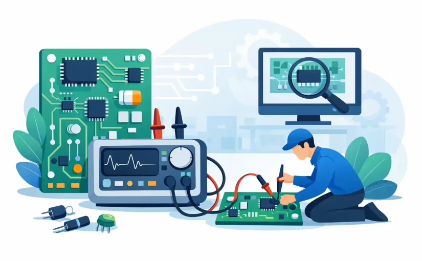
A suspected 0402 capacitor can stop a production repair as effectively as a visibly damaged power transistor. The difference is that the capacitor may look perfect, sit between surrounding components, and produce a misleading reading with ordinary test leads. Component testers are designed to reduce that gap between a suspected part and a defensible measurement.
For PCB repair, incoming inspection, rework verification, and design troubleshooting, the useful tester is not simply the one that recognizes the greatest number of component types. It is the instrument that makes reliable contact, applies an appropriate test signal, reports the relevant electrical parameter, and lets the operator recognize when an in-circuit result needs further investigation.
What Component Testers Need to Measure
A general-purpose digital multimeter remains necessary for voltage, continuity, and many resistance checks. But it is not a replacement for a component measurement instrument. A meter may confirm that a resistor is not open, for example, while providing little help in determining whether a capacitor has excessive ESR or whether an inductor is within its required inductance and loss range.
A capable component tester should support the measurements technicians use to separate likely good parts from likely failures: resistance, capacitance, inductance, impedance, ESR, and dissipation factor or quality factor where applicable. Automatic component identification is valuable because it speeds routine work, particularly when sorting loose parts or checking unmarked SMD devices. It should not be treated as the final diagnosis by itself.
The measurement conditions matter as much as the displayed value. Capacitance measured at a low frequency can look acceptable even though the part behaves poorly at the switching frequency of the circuit. Inductors, ferrites, and low-value capacitors can also produce materially different results as frequency changes. For this reason, selectable test frequencies are a practical diagnostic capability, not a specification added for appearance.
Test Frequency Changes What You Can See
A component is not electrically identical at every frequency. Capacitors include equivalent series resistance and inductance. Inductors have winding resistance, core losses, and parasitic capacitance. Even resistors can become reactive at high enough frequencies. The frequency used by the tester determines which part of that behavior is emphasized.
For general inspection, a lower test frequency may be sufficient. For switch-mode power supplies, RF-adjacent circuits, fast digital designs, and small-value passive components, higher-frequency measurement can reveal behavior that a low-frequency reading obscures. Instruments operating at 100 kHz or 250 kHz provide a more relevant test condition for many modern PCB applications than basic low-frequency LCR measurement alone.
There is still no single best frequency for every component. A technician investigating bulk electrolytic capacitors may prioritize ESR and capacitance at conditions related to the power circuit. Someone validating a small ceramic capacitor may need a test frequency that better reflects its intended operating range. Good component testers provide the measurement capability; experienced users select conditions that fit the circuit and the component technology.
Accuracy Is Only Useful With Controlled Contact
A 0.1% or 0.2% basic accuracy specification has value when the test setup supports it. Oxidized pads, loose probe pressure, contaminated tweezer tips, and long unshielded leads can introduce enough error to overwhelm a precise instrument, especially on low-resistance, low-capacitance, or low-inductance parts.
For loose components, short connections and proper open/short compensation are essential. For populated boards, stable probing is equally important. Tweezer-style probes are particularly effective for small SMD components because both contacts can be placed directly across the part without the hand movement and lead clutter associated with two separate probes.
This is why ergonomics belong in the measurement discussion. A test instrument that is technically accurate but awkward to position on an 0201 or 0402 package will not produce consistently accurate field results. Direct component access, insulated tips, replaceable probes, and accessories sized for PCB work all affect repeatability.
In-Circuit Testing: Fast Screening, Not Automatic Proof
In-circuit testing is one of the main reasons to use dedicated component testers. It can identify a shorted capacitor, confirm a resistor value, or compare a suspect component against identical parts nearby without removing every device from the board. That speed is valuable in repair environments where unnecessary rework creates its own risks.
However, a component on a populated PCB is connected to the rest of the circuit. Parallel resistors can lower the apparent resistance. Multiple capacitors on a rail can raise the apparent capacitance. Semiconductor junctions and IC input networks can affect measurements in ways that are not obvious from the board layout.
A disciplined approach is to use the in-circuit measurement as evidence, then compare it with the schematic, a known-good board, or neighboring channels. If the reading is clearly abnormal, the fault path may be obvious. If it is close to the expected value but remains questionable, lift one terminal or remove the component and measure it out of circuit. The correct decision depends on circuit topology, the cost of rework, and the level of certainty required.
Choosing a Tester for the Actual Workbench
The right instrument depends on whether the work is repair, manufacturing, design verification, or education. A compact automatic tester may be appropriate for field technicians who need fast identification and basic values. Engineering labs and quality-control teams often need greater basic accuracy, selectable test frequencies, calibration documentation, and data capture for traceable results.
When comparing component testers, evaluate the complete measurement workflow rather than a single headline specification. Four questions usually expose the practical differences:
- What component parameters and ranges can the instrument measure at relevant test frequencies?
- Can it make repeatable contact with the package sizes and board density encountered in daily work?
- Does it support in-circuit diagnostics, including tools such as analog signature analysis or oscilloscope functions when needed?
- Can results be calibrated, documented, or transferred for reports and quality records?
For example, Bluetooth connectivity is useful when it shortens the path from a bench measurement to a saved record on a mobile device or PC. It is less valuable if data transfer is not part of the workflow. Similarly, integrated oscilloscope and analog signature analysis functions can accelerate fault isolation on boards where static LCR values alone do not explain the failure.
Siborg Systems designs handheld instruments around this direct-to-component workflow, including Smart Tweezers and LCR-Reader models that combine tweezer probing with professional LCR measurement. Model selection should still be based on required accuracy, frequency, connection method, and diagnostic functions rather than on instrument category alone.
Calibration Supports Repeatable Decisions
Calibration is not only a purchasing requirement for regulated labs. It establishes confidence that a result is comparable over time, across instruments, and between technicians. For manufacturing, service documentation, and formal test procedures, a NIST Traceable Calibration Certificate can be a necessary part of the instrument record.
Users should also maintain the conditions that preserve performance. Keep probe tips clean, inspect insulation and mechanical alignment, perform compensation as specified, and protect the instrument from damage caused by charged capacitors or energized circuits. Before measuring a component, confirm that the circuit is powered down and that stored energy has been safely discharged.
Build a Faster Diagnostic Routine
The fastest troubleshooting process does not begin by measuring every component. Start with the fault symptom and isolate the likely section of the circuit. Check supply rails, obvious shorts, heat damage, and repeated circuit channels. Then use component-level measurement to compare suspected parts with expected values or known-good equivalents.
For capacitors, examine capacitance and ESR in the context of the application. For resistors, verify value and look for parallel-path effects before declaring a part out of tolerance. For inductors, consider DC resistance, inductance, and the frequency at which the reading was taken. For LEDs and semiconductors, use the appropriate test mode and verify polarity, forward behavior, or junction response rather than relying on a generic resistance measurement.
This approach prevents a common failure mode in PCB repair: replacing the first part that produces an unusual reading. A component tester is most effective when it helps narrow the evidence, not when it substitutes a display value for circuit analysis.
The best measurement habit is simple: make the reading easy to trust. Use the correct test frequency, make clean direct contact, account for the surrounding circuit, and document results when the job requires traceability. That discipline turns a handheld tester from a convenient accessory into a practical diagnostic instrument.