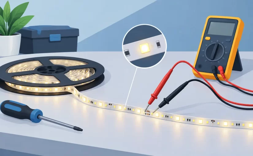
A failed LED string rarely fails at random. Whether it is a backlight strip, architectural fixture, sign module, or decorative string, the fault is usually an open LED, a shorted LED, a damaged interconnect, or a driver operating outside its intended range. Knowing how to troubleshoot LED strings means separating the LED load from the driver, then making measurements that explain the actual failure rather than simply replacing parts until light returns.
Start by identifying whether the assembly is powered by a low-voltage constant-voltage source, a constant-current driver, or a mains-connected supply. That distinction determines what a normal measurement looks like and how the string should be tested. Do not connect a bench supply, multimeter diode mode, or LED tester to a live mains-powered circuit.
Establish the LED string topology first
An LED string may contain all LEDs in series, multiple series strings in parallel, or series groups with a resistor or current regulator on each branch. The expected forward voltage follows from that topology. A white LED commonly requires roughly 2.7 V to 3.4 V at its rated current, but this is not a fixed value. Red, amber, blue, ultraviolet, and infrared devices have different forward-voltage ranges, while temperature and test current also affect the reading.
Count the LEDs in a known series path and compare that count with the driver output rating. Ten white LEDs in series, for example, will normally require a driver compliance voltage in the neighborhood of 30 V. If the driver is rated for 18 V to 36 V constant-current operation, that is plausible. If it is a 12 V constant-voltage supply, the circuit must contain parallel branches, current-limiting resistors, or a switching regulator.
This initial check prevents a common error: treating a constant-current string as though it were a 12 V lamp circuit. Applying a fixed voltage without current limiting can damage otherwise good LEDs.
Inspect the physical fault before measuring
Visual inspection is not a substitute for measurement, but it is efficient. Look for darkened LED packages, cracked solder joints, lifted pads, overheated resistors, corroded connector contacts, broken flexible-PCB traces, and discoloration near the driver. In outdoor strings, water entry at wire-to-module joints and molded connectors is often more relevant than the LEDs themselves.
A single visibly burned LED can be the original failure or the consequence of a driver fault. Check the surrounding circuit before installing a replacement. If multiple LEDs have darkened, verify driver current and thermal management. Replacing only the most obvious failed device may produce a short-lived repair.
With power removed, gently flex suspect cable sections while monitoring continuity where practical. Intermittent open conductors are especially common near strain-relief points, corners of aluminum-core LED boards, and repeated bend locations in flexible strips.
Verify the driver with the correct load condition
Measure the driver input first. Confirm that AC input, DC supply voltage, fuse condition, connector polarity, and control signals such as enable or dimming are present. Then assess the output according to driver type.
A constant-voltage supply should remain close to its rated output with a representative load connected. A substantial voltage collapse usually indicates overload, a shorted branch, inadequate input power, or a failing supply. An unloaded reading alone can be misleading, particularly with switching supplies that regulate differently at light load.
A constant-current driver behaves differently. Its output voltage changes as needed to force the programmed current through the LED load, up to its compliance limit. An open LED string may make the output rise toward maximum voltage, pulse, or shut down and retry. A shorted or low-forward-voltage load may cause the driver to reduce output voltage while maintaining current. Measure current only with a meter and connection method rated for the expected voltage and energy source.
If the driver output is cycling, do not assume the driver is defective. Many LED drivers enter hiccup protection when they detect an open circuit, short circuit, overtemperature condition, or load outside the allowable voltage range.
Test individual LEDs without overdriving them
For a disconnected low-power string, a multimeter diode test can identify obvious open or shorted LEDs. Place the probes across one LED in the forward direction. A healthy red or amber LED may illuminate faintly and show a forward-voltage reading. Many white and blue LEDs require more voltage than a standard meter diode function can provide, so a non-reading does not automatically prove failure.
A dedicated LED tester is more effective for longer series strings because it can supply controlled current at a higher voltage. Begin at the lowest appropriate current. The purpose is to confirm conduction and locate the interruption, not to operate the LEDs at normal brightness. On a long string, a tester that indicates no current flow usually points to an open LED, open trace, disconnected wire, or reverse-polarity test connection.
When testing surface-mount LEDs on a populated board, probe placement matters. Oxidized pads, solder mask, and closely spaced components can create false readings. Fine insulated probes or tweezer-style probes provide more repeatable contact than standard large test leads. A component measurement instrument such as Siborg’s Smart Tweezers can also help verify nearby resistors, capacitors, and damaged interconnect components without removing every part from the board.
Find opens, shorts, and bypassed LEDs
An open LED is the most common reason a series string goes dark. In diode mode, it may show overload in both directions. In a powered string, voltage often appears across the failed device or across the section containing it, while no current flows through the complete path. Test from section to section rather than probing every device immediately. Halving the suspected path repeatedly is faster on long strips and panels.
A shorted LED can be less obvious because the remaining LEDs may still illuminate. The symptom may be a dark spot in a backlight, uneven brightness, excess current in a constant-voltage branch, or a driver that cannot regulate correctly. A shorted device often reads very low resistance or near-zero voltage in both probe directions, though parallel circuit paths can mask the result.
Some products intentionally include shunt devices across LEDs. These bypass a failed open LED so the rest of the string remains lit. A dim or dark individual LED in an otherwise operating string may therefore indicate a valid shunt action, not a wiring fault. Replace the LED and inspect the shunt circuit if uniform illumination is required.
Check current, not just light output
An LED can illuminate and still be part of a failing assembly. Measure branch current and compare parallel branches under the same operating condition. A branch drawing significantly more current may contain a shorted LED, incorrect resistor value, or regulator fault. A low-current branch may have increased resistance in a connector, cracked solder joint, degraded resistor, or partially failed LED.
Use voltage measurements across current-setting resistors to calculate current from Ohm’s law. This is often safer and more informative than opening a high-current path to insert an ammeter. On constant-current drivers, verify that measured current is within the LED board’s specified range. Excess current raises junction temperature, shifts color, accelerates lumen loss, and can cause repeated field failures.
Thermal behavior should also be evaluated after the electrical fault is repaired. An infrared camera is useful, but even a careful temperature comparison can reveal a hot resistor, regulator, or LED package. A replacement LED with the wrong forward voltage, package thermal resistance, bin, or current rating can create a new imbalance in the string.
Confirm the repair under realistic operation
After replacing a component or repairing a trace, test the assembly first at controlled current or reduced input power where possible. Then operate it at normal voltage, normal dimming level, and normal enclosure condition. Observe startup, steady-state current, brightness uniformity, and driver temperature long enough for thermal regulation to stabilize.
Document the failed component location, forward-voltage behavior, branch current, and driver output. That record matters in production and field service because repeated failures often reveal a design, assembly, or environmental issue rather than isolated defective LEDs.
The most efficient LED-string repair is not the one that restores light fastest. It is the one that identifies whether the LED, interconnect, current-control circuit, or operating conditions caused the failure – and verifies that the repaired string will remain within its electrical and thermal limits.