How to Use Kelvin Probes for Accurate PCB Tests

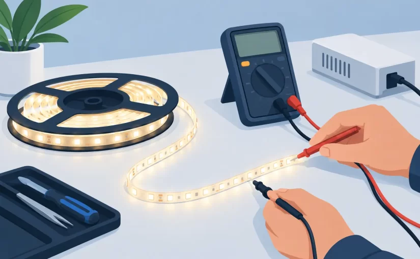
A 0.05 ohm contact error is insignificant on a 10 kilohm resistor. On a 0.10 ohm current-sense resistor, it can invalidate the measurement. That is the practical reason to learn how to use Kelvin probes: they separate the current path from the voltage-sensing path, removing much of the error caused by test leads, clips, and probe contact resistance.

Kelvin probing is not a substitute for sound measurement practice. It is a four-terminal technique that improves results when the device under test has low resistance, low impedance, or when lead and contact resistance are a meaningful part of the reading. Used correctly, it is valuable for current shunts, battery tabs, cable joints, relay contacts, PCB traces, low-value resistors, and capacitor ESR measurements.

How to Use Kelvin Probes: The Four-Wire Principle

A conventional two-wire measurement sends test current through a pair of leads and measures voltage through those same leads. The instrument therefore sees the resistance of the component plus the resistance of the leads, connections, oxidation, and probe pressure.

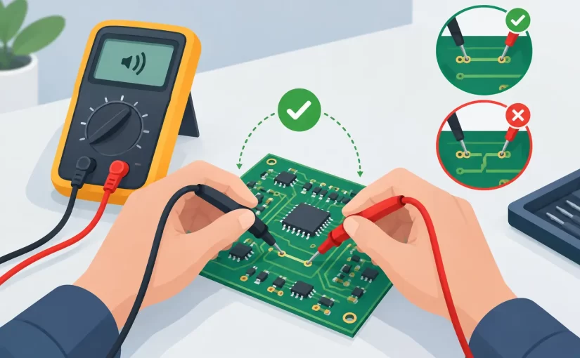
Kelvin probes use two separate pairs of conductors. The force pair applies a known test current to the component. The sense pair measures the voltage directly at the component terminals. Because the sensing input draws very little current, voltage drop in the sense leads is negligible. The instrument calculates resistance from the voltage measured at the device under test and the known test current.

For a two-terminal resistor, the connection order is straightforward: force current enters one terminal and returns from the other, while the sense contacts touch those same two terminals as close to the resistor body or solder joints as possible. Many Kelvin clips and Kelvin test tweezers place force and sense contacts in one compact jaw, making this arrangement faster and more repeatable.

The method does not make every reading automatically accurate. If the sense contacts are placed on a PCB trace several centimeters away from the component, the measured trace resistance is still included. That may be desirable when checking an interconnect, but it is not the same as measuring the component alone.

Select the Right Instrument Mode First

Start by choosing the measurement function that matches the fault or component. A DC low-resistance mode is appropriate for shunts, wiring, contacts, and trace continuity where resistance is the primary concern. An LCR meter is more suitable for inductors, capacitors, and resistors measured at a specified AC test frequency. ESR testing uses an AC method intended to characterize a capacitor’s effective series resistance.

Test frequency matters. A capacitor can show a low ESR at one frequency and a different value at another, particularly with electrolytic, polymer, and ceramic technologies. Inductors and ferrite components can also be frequency-dependent. Use the frequency required by the component specification or the troubleshooting condition, rather than treating a single reading as universal.

Before connecting, check four practical conditions:

  • The circuit is powered down and discharged.
  • The instrument range and test function suit the expected value.
  • The probes, tips, and fixture are clean and mechanically sound.
  • The component can be measured in circuit without a parallel path distorting the result.

A powered circuit can damage an LCR or ESR instrument and produce misleading results. Stored charge in large capacitors is equally problematic. Discharge capacitors through an appropriate resistor and verify the remaining voltage with a suitable meter before applying Kelvin probes.

Compensate the Probes and Fixture

Four-wire measurement reduces lead resistance effects, but compensation is still required for the best results, especially with LCR and ESR measurements. The exact procedure depends on the instrument, but it generally includes open and short compensation.

Open compensation measures residual capacitance and leakage associated with the fixture and probe geometry when the tips are separated. Short compensation measures residual resistance and inductance when the force and sense contacts are connected together at the probe tips. The instrument stores these values and subtracts or corrects for fixture effects during measurement.

Perform compensation using the same probes, tips, and cable arrangement that will be used for the measurement. If you change from Kelvin clips to test tweezers, replace probe tips, or alter a long cable layout, repeat the procedure. At higher test frequencies, even small changes in contact geometry and lead routing can affect parasitic inductance and capacitance.

For low-resistance work, a short check also reveals a damaged lead or contaminated contact. A compensated fixture should produce a stable near-zero reading when its Kelvin contacts are properly shorted. If the value wanders, inspect the probe jaws, cable strain relief, connector seating, and oxidation on the contact surfaces.

Make Contact at the Correct Measurement Plane

The measurement plane is the exact point where the instrument senses voltage. It determines what is included in the result.

When measuring a low-value SMD resistor, place the Kelvin contacts directly on the two solder fillets or on exposed terminal metallization. Avoid contacting distant vias or adjacent copper unless the trace resistance is part of the test objective. For a cable assembly, place the sense contacts at the two points whose resistance must be verified, not at convenient locations farther up the harness.

Contact pressure should be firm enough to break through light surface films but not so high that it damages pads, small components, or conformal coating. On fine-pitch boards, sharp and well-aligned tips are more useful than excessive force. A stable fixture or tweezer-style probe reduces hand movement and helps maintain repeatable contact on 0201, 0402, and similar small packages.

Kelvin probes are especially effective when the force contacts are outside the sense contacts, or when a purpose-built clip maintains the correct geometry. Do not improvise by placing two ordinary probe tips on each terminal unless spacing and stability allow the force and sense points to remain distinct. On small components, dedicated Kelvin tweezers or closely spaced four-wire probe accessories are usually the practical solution.

Measure In Circuit With Caution

In-circuit Kelvin testing is fast, but the board can create parallel paths that are invisible at first glance. A 1 ohm resistor may be connected to other resistors, semiconductor junctions, IC inputs, or copper planes that alter the reading. A capacitor ESR measurement may be influenced by parallel capacitors, regulators, or protection devices.

Use the schematic and board layout to decide whether the reading is meaningful. If the measured value is lower than expected, look for parallel components or alternate current paths. If it is higher, inspect solder joints, cracked terminations, corroded vias, fuses, connectors, and damaged copper. A comparison with an identical channel or known-good board is often more useful than comparing only against a nominal component value.

For critical component verification, isolate one terminal or remove the component. This takes more time but eliminates ambiguity. The appropriate choice depends on the cost of a false diagnosis, the accessibility of the component, and whether the board is a repair unit, production sample, or qualification article.

Reading Low Resistance, ESR, and Inductance Results

A good Kelvin reading is stable, repeatable, and technically plausible. Take several readings while lightly repositioning the probe. If the value changes significantly, suspect contact quality before declaring the component defective. Oxidation, flux residue, worn probe tips, and insufficient jaw alignment commonly cause unstable low-ohm readings.

For resistors, compare the result with the nominal value and tolerance, while accounting for temperature coefficient and in-circuit paths. For current shunts, measure at the intended pad locations because milliohms of copper can matter. For relay contacts or connectors, measure under the specified mechanical state and, where appropriate, under a test current representative of service conditions.

For capacitors, do not interpret ESR without considering capacitance, voltage rating, technology, temperature, and test frequency. A low ESR value is not automatically good if capacitance has fallen substantially. Likewise, ceramic capacitors may have very low ESR while still exhibiting a crack or DC-bias-related performance issue that requires another test method.

Advanced handheld LCR instruments can combine Kelvin-compatible probing with higher test frequencies and component identification functions. In PCB repair, compact tweezer-style measurement can reduce the time required to move from suspected component to verified result, provided the operator still controls the measurement plane and understands the surrounding circuit.

Common Kelvin Probe Errors

The most frequent error is assuming four wires eliminate every source of uncertainty. Kelvin measurement removes most voltage error caused by the force leads, but it cannot correct for poor sense contact, a contaminated pad, thermal effects, electromagnetic interference, or an unsuitable test frequency.

Another common problem is crossing or misidentifying force and sense connections on separate clips. Follow the instrument labeling and keep each terminal’s force and sense contacts paired at the same end of the device under test. On long leads, route force and sense conductors together and avoid large loops that can pick up noise, especially during AC impedance measurements.

Finally, protect the probes. Kelvin tips are precision contacts, not general-purpose scraping tools. Clean them with an electronics-safe method, replace worn points, and verify compensation before measurement sessions where milliohm-level repeatability matters.

A Kelvin probe earns its place on the bench when the difference between a component fault and a connection fault is only a few milliohms. Put the sense contacts at the true test point, compensate the fixture, and let the measurement answer the question you actually need to ask.

Electronics Repair Tools for PCB Diagnosis

A board can look perfect under magnification and still fail because of one 0402 capacitor, a damaged MLCC, or an inductor that has shifted outside its working range. Effective electronics repair tools shorten the path from symptom to component-level evidence. For PCB diagnosis, tool selection is less about owning the largest collection and more about making reliable measurements quickly, safely, and at the frequencies that matter.

Electronics Repair Tools Start With the Measurement Task

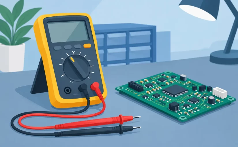
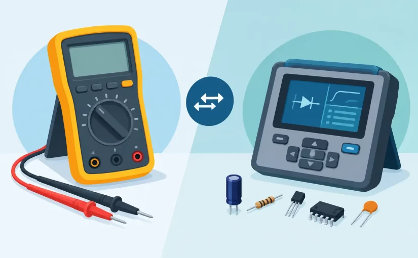
A digital multimeter remains the first instrument most technicians reach for. It is appropriate for confirming supply rails, continuity, diode junction behavior, DC resistance, current draw, and basic voltage references. It is not, however, a complete component analyzer. A multimeter may indicate that a capacitor is not shorted while providing no useful indication of its capacitance, ESR, dissipation factor, or behavior at a relevant test frequency.

That distinction matters on densely populated boards. Switching power supplies, RF sections, display drivers, battery-management circuits, and high-speed digital assemblies often depend on small passive components whose faults are not visible through DC checks alone. An LCR meter or ESR meter adds the measurements needed to assess resistors, capacitors, and inductors as components rather than simply as conductive paths.

The correct instrument depends on the failure mode being investigated. If a rail is absent, start with voltage and continuity. If the rail is present but unstable, evaluate the capacitors and inductors supporting that circuit. If a signal path is distorted or intermittent, waveform inspection and analog signature comparison can identify differences between a known-good and suspect section. Good troubleshooting follows the circuit, rather than forcing every question through one meter.

Accuracy Is Only Useful at the Right Frequency

Basic accuracy is a meaningful specification, but it should not be considered in isolation. A 0.1% or 0.2% basic accuracy specification supports confident comparison and verification when the test conditions match the component and application. Test frequency is equally important, particularly for capacitors and inductors.

A capacitor measured at a low frequency can appear acceptable while exhibiting excessive loss or impedance under the operating conditions of a switching circuit. Likewise, inductance readings can vary with frequency, DC bias, core material, and the component’s connection to the surrounding circuit. Instruments with 100 kHz or 250 kHz test capability provide more useful characterization for many modern PCB applications than meters limited to low-frequency measurement.

In-circuit readings still require judgment. Parallel components, semiconductor junctions, control ICs, and alternate current paths can influence the result. A reading that differs from the marking or schematic is not automatically proof of a defective part. Compare equivalent locations where possible, isolate one end of the component when the diagnosis requires certainty, and account for the circuit topology before ordering a replacement.

Direct Access Matters More Than Lead Length

Conventional probe leads are flexible and familiar, but they become inefficient on boards populated with 0201, 0402, and 0603 components. The technician must stabilize the board, place two probes on tiny terminations, avoid bridging adjacent pads, and keep the test contact consistent long enough for the reading to settle. That process is slow, especially during repetitive inspection or production rework.

Tweezer-style LCR instruments address this access problem directly. Insulated tips provide two-point contact at the component terminals, allowing the operator to pick up loose SMD parts or measure accessible devices on the board. The mechanical design is not a convenience feature alone. It improves repeatability by reducing hand movement and making the contact geometry more consistent from measurement to measurement.

For repair work, tip selection also affects results. Fine tips improve access between tightly spaced parts but can be easier to damage. Wider or more durable tips can be better for frequent work on larger passives. Replaceable probing accessories allow one instrument to adapt to bench diagnosis, field service, loose-component verification, and populated-board inspection without compromising the primary measurement method.

Siborg Systems instruments such as Smart Tweezers and LCR-Reader models are designed around this direct-contact workflow, combining handheld SMD access with professional LCR measurement capabilities. The relevant configuration depends on whether the priority is entry-level identification, higher test frequencies, Bluetooth data transfer, or expanded diagnostic functions.

Build a Bench Around Complementary Functions

A capable repair bench does not need duplicate instruments. It needs coverage across the measurements that separate common faults. Start with a quality digital multimeter for electrical safety checks and DC diagnosis, then add specialized tools where they remove uncertainty.

An LCR meter is the primary addition for passive-component work. Look for clear measurement of capacitance, resistance, inductance, ESR, dissipation factor, and impedance, along with selectable test conditions where applicable. Automatic component identification is valuable when sorting unknown loose parts, but manual mode remains important when a specific parameter and frequency are required.

An ESR meter is particularly useful when evaluating capacitors in power circuits. High ESR can cause ripple, poor regulation, startup failure, heat, or intermittent operation even when nominal capacitance appears close to specification. This is especially relevant for electrolytic capacitors, but low-ESR ceramic and polymer capacitors also require measurement conditions appropriate to their application.

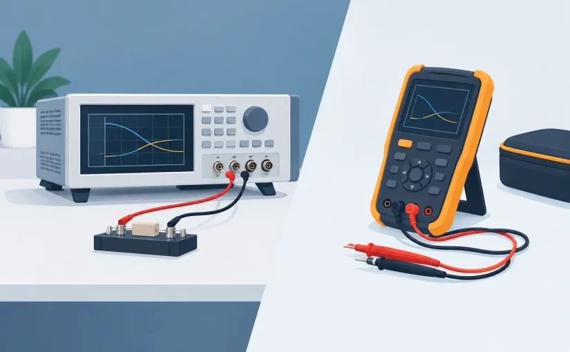
Oscilloscope capability belongs on the bench when a fault involves timing, ripple, switching activity, serial communications, or intermittent signal behavior. For compact field work, integrated oscilloscope functions can provide a fast first view. A dedicated bench oscilloscope remains preferable when bandwidth, multiple channels, triggering depth, or detailed waveform analysis is required. The trade-off is straightforward: integrated functions improve portability, while separate instruments provide broader analysis capacity.

Analog Signature Analysis adds another comparison method. By applying an AC stimulus and observing the resulting current-voltage signature, a technician can compare devices or circuit nodes without powering the board. It is not a replacement for LCR measurement or a scope, but it can help locate shorts, opens, leakage paths, and abnormal semiconductor behavior when a known-good comparison point exists.

Protect the Board and the Measurement

Precision instruments cannot compensate for poor probing practice. Before measuring a board, verify the power state, identify energy-storage capacitors, and discharge circuits where necessary. An ESR or LCR measurement performed on a charged capacitor can damage the instrument, the board, or both.

ESD control is equally practical. Use a grounded work surface and wrist strap when handling static-sensitive assemblies, particularly boards containing CMOS logic, RF front ends, memory devices, and fine-pitch controllers. Keep probe tips clean and inspect them for bent points, worn insulation, or contamination that can cause unstable contact.

When troubleshooting powered circuits, choose probes and accessories rated for the voltage and environment involved. Keep one hand clear of the assembly where appropriate, secure the board so it cannot shift, and avoid relying on improvised metal tools near exposed conductors. Fast diagnosis is valuable only when it does not introduce a second fault.

Make Results Repeatable and Defensible

Repair decisions often move beyond the individual technician. Manufacturing teams may need incoming inspection records. Service organizations may need proof of a completed repair. Engineering groups may need to compare a returned board against reference data. In these cases, repeatability and documentation are part of the tool requirement.

Calibration support is one consideration. A NIST Traceable Calibration Certificate provides documented confidence that an instrument has been verified against recognized standards. It does not eliminate the need for careful operation, open and short compensation, or routine inspection of probes and tips. It does provide a traceable basis for measurements used in quality systems, customer reports, and controlled repair processes.

Bluetooth-enabled instruments can further improve workflow when measurements must be captured instead of transcribed. Recording values to a mobile device or PC reduces transcription errors, supports comparison over time, and creates a clearer service record. Wireless transfer is most useful when it fits an established process. For a single loose component, reading the display may be faster. For batch inspection or recurring failure analysis, captured data becomes a practical advantage.

Choose Tools for the Work You Actually Perform

A technician repairing consumer electronics may prioritize portability, SMD access, capacitance, ESR, and diode testing. A manufacturing quality team may place more weight on accuracy, calibration documentation, repeatable fixtures, and data capture. An engineer working with power electronics may require higher-frequency LCR measurement, waveform visibility, and accessories that tolerate larger components and higher-energy environments.

Avoid selecting tools solely by the longest feature list. A high-frequency LCR meter is valuable when the application calls for it, but it may be unnecessary for occasional through-hole repair. Bluetooth is useful when measurements need to be retained, not simply because it is available. The best electronics repair tools are the ones that reduce uncertainty at the exact point where your current workflow slows down.

Keep the bench organized around that principle. Measure the circuit state first, test passive components under meaningful conditions, use direct-contact probes where board density demands them, and document results when the repair must be repeatable. A technician who can trust the measurement can make the next decision with speed rather than guesswork.

Impedance Measurement Guide for PCB Work

A 10 uF ceramic capacitor can appear healthy at 1 kHz and become the source of a power-rail problem at a higher operating frequency. A resistor can measure correctly in DC resistance mode while its parasitic inductance affects a high-speed circuit. This impedance measurement guide focuses on obtaining readings that represent component behavior under real test conditions, not merely a number displayed by an instrument.

What impedance measurement actually measures

Impedance is the opposition a component or network presents to alternating current. It includes resistance and reactance, so it is expressed as a complex quantity with magnitude and phase. Resistance dissipates energy. Capacitance and inductance store and release energy, producing reactance that changes with frequency.

For a resistor, impedance may remain close to its stated resistance over a useful frequency range. For a capacitor, capacitive reactance decreases as frequency rises. For an inductor, inductive reactance increases with frequency. Real components also contain parasitic resistance, inductance, and capacitance, which eventually dominate the result.

That distinction matters during PCB diagnosis. Measuring only DC resistance cannot show capacitor ESR, inductor loss, resonance, or the frequency-dependent loading caused by a component package and its board layout. An LCR meter applies an AC test signal, measures voltage and current, and calculates the selected equivalent parameters at a defined test frequency.

Select the frequency before interpreting the value

A valid impedance reading begins with a relevant frequency. Component data sheets commonly specify capacitance, inductance, dissipation factor, Q, or ESR at a stated frequency and test level. Measuring at a different condition is not necessarily wrong, but it answers a different question.

For general component identification, 100 Hz, 1 kHz, or 10 kHz can be appropriate starting points. Higher frequencies are more useful when evaluating low-value capacitors, small inductors, RF-adjacent circuits, switching power supplies, and the parasitic behavior of SMD components. A 100 kHz or 250 kHz measurement capability can reveal behavior that is hidden at audio-range test frequencies.

The correct choice depends on the fault and the component. A bulk electrolytic capacitor in a low-frequency filter may be assessed effectively at lower frequencies, with ESR included in the evaluation. A multilayer ceramic capacitor supporting a fast digital rail should be checked closer to the frequencies where low impedance is required. Do not expect a single frequency to characterize every component.

Watch for self-resonance

Every physical capacitor and inductor has a self-resonant frequency. A capacitor behaves capacitively below resonance, reaches minimum impedance near resonance, and appears inductive above it. An inductor behaves inductively below resonance and becomes increasingly capacitive above it.

If a reading seems inconsistent with the component marking, check the test frequency before assuming the part has failed. At higher frequencies, a small change in fixture position, lead length, or PCB trace geometry can also affect the measurement.

Choose the right equivalent circuit

Most LCR instruments report component values using series or parallel equivalent circuits. This selection affects the displayed resistance, loss, Q, and dissipation factor, especially when the device under test has significant loss.

A series model represents the component as an ideal reactance in series with a resistance. It is commonly useful for low-impedance capacitors and inductors, where lead resistance, winding resistance, or ESR is naturally modeled in series. A parallel model represents an ideal reactance alongside a resistance and is often appropriate for high-impedance components and leakage-dominated behavior.

As a practical rule, use the model specified by the component manufacturer whenever possible. If no specification is available, compare the measured impedance magnitude with the instrument’s applicable model guidance. Recording only “10 nF” is incomplete when loss and frequency are relevant. Record capacitance or inductance, the selected series or parallel mode, test frequency, and the associated ESR, D, or Q value.

Establish a controlled measurement setup

The instrument, fixture, and operator form part of the measurement system. This is particularly true for milliohm-level ESR, low-inductance capacitors, and small SMD parts. Poor contact pressure or oxidation can produce an apparent component defect.

Start by allowing the meter to stabilize according to its operating instructions. Use the shortest practical test path and select probes or tweezers that match the component size. Dedicated tweezer-style contacts reduce loop area and make it possible to contact opposing SMD terminations directly, rather than chasing a small part with conventional test leads.

Perform open and short compensation with the same fixture and approximate measurement geometry used for the test. Open compensation reduces the influence of stray capacitance. Short compensation reduces residual lead resistance and inductance. Compensation is not optional housekeeping when measuring very small values. It is the reference that separates the fixture from the device under test.

For repeatable production or laboratory work, control contact location and pressure. A probe touching the end cap of a chip capacitor may not produce the same result as one contacting a nearby solder fillet, especially at higher frequencies. Use a holder, fixture, or consistent technique when measurements will be compared across operators or lots.

Measure loose parts first when possible

A loose component measurement provides the clearest indication of the part itself. Remove the component from static-sensitive packaging only with suitable ESD controls, identify its value and package, compensate the fixture, and take readings at the frequencies that match the intended application or data sheet conditions.

For loose parts, confirm more than the nominal value. A capacitor may show the correct capacitance but excessive ESR. An inductor may measure its stated inductance but have poor Q or higher-than-expected winding resistance. A resistor can pass a low-frequency resistance check while showing unexpected inductive behavior at the circuit’s operating range.

Smart Tweezers and LCR-Reader instruments are designed for this direct-contact workflow, allowing technicians to identify and measure SMD components without changing from long test leads to a separate fixture. The benefit is not just speed. Short, controlled contacts reduce the uncertainty added by loose probe wiring.

Understand the limits of in-circuit impedance tests

In-circuit testing is fast, but the reading represents every available path connected to the probes. A capacitor measured across a power rail may be in parallel with several other capacitors, integrated circuits, protection devices, and converter stages. A resistor can be shunted by another branch. An inductor can be affected by semiconductor junctions or transformer windings.

Use in-circuit impedance measurement as a diagnostic comparison tool. Compare identical channels, known-good boards, or equivalent locations on the same board. A significantly lower impedance on one rail may indicate a shorted capacitor or semiconductor. A substantially different ESR reading may identify a degraded capacitor, but confirm the result after isolating the part if parallel paths are plausible.

Power must be removed before ordinary passive-component measurement. Discharge capacitors safely and verify that stored voltage is absent. An energized board can damage the instrument, create misleading readings, or place an active circuit in an unintended state.

A practical isolation strategy is to lift one terminal only when necessary. This removes most parallel ambiguity while minimizing rework compared with complete removal. For dense assemblies, inspect the schematic or board topology first. Knowing which components share a node prevents wasted troubleshooting time.

Read ESR, D, and Q in context

ESR is especially useful for capacitors in power conversion, filtering, and decoupling roles. High ESR increases ripple voltage, heat, and losses. However, a low ESR value is not automatically good if it is inconsistent with the capacitor technology or if the measurement frequency is inappropriate.

Dissipation factor, or D, expresses loss relative to reactance. Lower D generally indicates lower loss in capacitive measurements. Quality factor, Q, is the inverse relationship used frequently for inductors and resonant components. A falling Q can point to core loss, winding loss, damage, or test conditions outside the part’s intended range.

Use the specification as the acceptance limit whenever one exists. Generic pass-fail values are unreliable because a polymer capacitor, aluminum electrolytic, MLCC, ferrite inductor, and air-core coil are designed for different impedance and loss characteristics.

Document measurements that others can use

A useful record includes the component reference designator, nominal value, measured value, test frequency, test level if available, equivalent circuit mode, fixture compensation status, and whether the test was in circuit or out of circuit. Add board revision and ambient conditions for failure analysis or quality work.

Bluetooth or PC-connected measurement tools can reduce transcription errors when many readings must be captured, compared, or attached to a service report. Digital capture is most valuable when it preserves the conditions behind the number. A spreadsheet of capacitance values without frequency, mode, and test location can be difficult to interpret later.

Accurate impedance work is a matter of matching the meter, frequency, fixture, and circuit context to the question being asked. When a result is surprising, treat it as evidence to investigate rather than an immediate verdict on the component.

LED Testers for Accurate PCB Diagnostics

A dim display, an intermittent status indicator, or a dark LED backlight strip can turn a straightforward repair into an extended fault-isolation job. LED testers reduce that uncertainty by applying a controlled test stimulus directly to the device or LED string, revealing polarity, illumination, and approximate forward voltage without requiring a powered circuit.

For PCB repair, production inspection, and field service, the useful question is not simply whether an LED lights. The instrument must apply an appropriate voltage and current, provide a meaningful reading, and let the operator reach the component without damaging fine pads, neighboring parts, or the LED itself.

What LED Testers Actually Measure

At the component level, an LED is a diode with a light-emitting junction. A tester forward-biases that junction. When the applied voltage exceeds the LED’s forward-voltage requirement and current is limited to a safe value, the device emits light. Reversing the connection should normally produce no illumination.

A basic LED test therefore establishes three practical facts: whether the device conducts in the expected direction, whether it emits light, and the approximate forward voltage at the applied current. These results are often enough to identify an open LED, reversed installation, damaged bond wire, or incorrect replacement part.

Forward voltage is not a fixed identification number. It varies with LED chemistry, current, junction temperature, binning, and optical color. A red indicator LED may conduct at a substantially lower voltage than a white or blue LED, while infrared emitters can function normally without visible light. Treat the displayed voltage as a diagnostic measurement, not as a complete part specification.

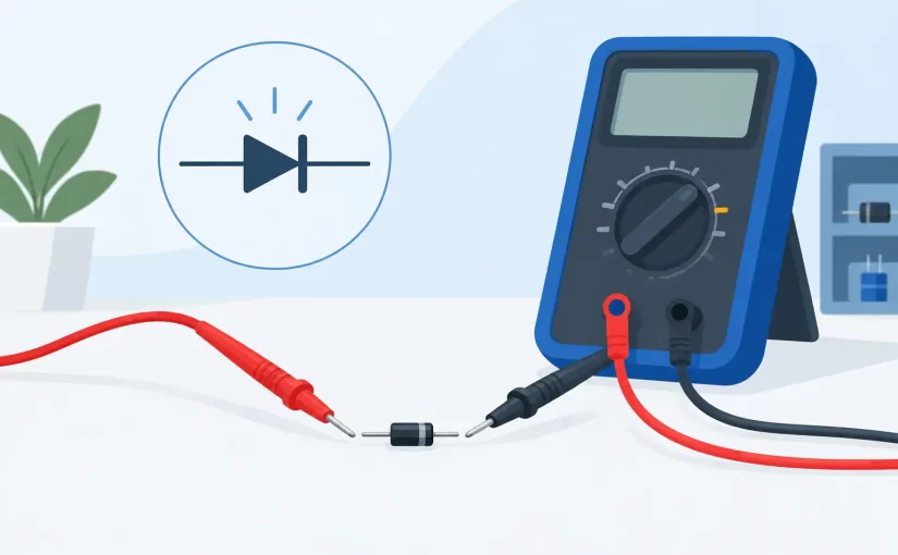
A multimeter diode mode can test many discrete LEDs, but it may not supply enough voltage to illuminate white, blue, ultraviolet, or series-connected LEDs. Dedicated instruments may provide a higher test-voltage range for these applications. That capability is valuable, but it also demands controlled current and disciplined probing.

Why Test Current and Voltage Range Matter

LEDs are current-driven devices. Once forward-biased, a small voltage change can create a significant change in current. A useful tester limits current rather than leaving the operator to infer safe conditions from an open-circuit voltage rating.

Low-current test modes are generally preferred for small indicator LEDs, SMD LEDs, and LEDs tested in sensitive assemblies. They can confirm conduction and polarity while reducing stress on the junction. A higher-voltage mode is necessary when checking multiple LEDs in series, such as display backlight strips, but the tester should still regulate current to prevent excessive dissipation.

Higher range is not automatically better. Applying a high-voltage LED test to a single small SMD LED can create unnecessary stress if the instrument’s current limit is unsuitable. Conversely, a low-range diode test can falsely suggest that a healthy white LED or a multi-LED string is open because the meter cannot reach its required forward voltage.

The correct mode depends on the device under test. Use low current and direct probes for individual board-mounted LEDs. Use a controlled higher-voltage range for strings only after confirming the string topology and disconnecting or isolating circuitry when required.

Reading a Dim or Uneven Result

An LED that lights dimly is not necessarily defective. Test current may be deliberately low, and some packages distribute light in a way that is difficult to see from a particular angle. Compare like components using the same test mode and viewing conditions.

Uneven brightness across a string can be more informative. A noticeably dim device, a device that requires a different voltage, or one that flickers during gentle probe movement may point to junction degradation, cracked solder joints, contamination, or a damaged trace. Repeat the test to separate a repeatable electrical result from an unstable mechanical connection.

In-Circuit LED Testing Has Limits

Testing an LED on a populated PCB is fast, but the surrounding circuit can change the result. Parallel diodes, driver IC outputs, protection networks, capacitors, and alternate current paths may make a good LED appear shorted, open, or unusually low in forward voltage.

Start with the board unpowered unless the service procedure specifically calls for powered measurements. Disconnect batteries, external adapters, and stored-energy sources. A tester’s applied voltage can interact unpredictably with active circuitry, particularly in LED drivers and display modules.

If an in-circuit measurement is ambiguous, compare it with an identical channel or neighboring LED. Symmetry is often the most useful reference in a repeated circuit. If no comparison point exists, isolate one LED lead or remove the component for a definitive test. That extra step is slower, but it avoids replacing a functioning part because of a misleading in-circuit path.

Backlight assemblies deserve special caution. Some strips contain integrated protection elements, multiple dies, or series and parallel arrangements that do not behave like a single discrete LED. A string tester can quickly identify whether a strip conducts and illuminates, yet it may not identify every marginal LED in a complex assembly. Localized voltage comparison and visual inspection remain useful follow-up methods.

Probe Access Determines Diagnostic Speed

The electrical capability of LED testers matters only when the probes can contact the device reliably. Conventional pointed leads are practical for through-hole LEDs, exposed test pads, connector pins, and larger strips. Fine SMD LEDs often require more controlled contact.

Sharp probes can slip off small pads and bridge adjacent conductors. For fine-pitch PCB work, insulated needle probes, spring probes, or tweezer-style accessories give better positional control. The goal is firm contact with minimal force. Pressing hard enough to flex a board can temporarily restore a cracked joint and conceal the fault being investigated.

Probe placement also affects the reading. Contact the actual LED terminals or known points in the same electrical path. Testing across a resistor, driver transistor, or connector section may show a voltage response without proving that the LED junction is intact. Board layouts, polarity marks, and circuit documentation should guide the measurement whenever available.

For production or recurring repair work, a repeatable fixture can be more valuable than faster handheld probing. A fixture establishes consistent contact pressure, orientation, and test conditions, improving pass-fail decisions across batches. Handheld tools remain the better choice for rework, field diagnostics, and varied board geometries.

Selecting LED Testers for the Workbench

Choose an instrument based on the LED types and failure modes encountered most often. A technician repairing consumer displays needs controlled higher-voltage testing for strips and modules. A PCB rework specialist may place greater value on low-current component testing, fine probes, and a compact form factor. Manufacturing teams may prioritize repeatable test conditions and documented inspection procedures.

Evaluate the instrument’s maximum test voltage, current-limit behavior, polarity indication, display readability, and supported LED configurations. Confirm whether the tester is intended for individual LEDs, series strings, or both. A visible-light result alone is insufficient when servicing infrared, ultraviolet, or enclosed optical devices, where current and voltage readings carry more diagnostic weight.

It is also useful to separate LED verification from broader component analysis. A dedicated LED function establishes junction behavior quickly. An LCR meter, ESR meter, or digital multimeter addresses the resistors, capacitors, inductors, supply rails, and driver components that may be responsible when a known-good LED does not operate in the circuit.

Siborg’s component-testing approach is built around direct access to small devices on boards, where probe control and repeatable measurements can save more time than a general-purpose test setup. For LED diagnostics, that same discipline applies: test the junction first, then follow the circuit path when the result does not match the observed failure.

A Practical Test Sequence

Begin by inspecting the LED and surrounding area under magnification. Look for discoloration, cracked lenses, lifted pads, corrosion, missing components, and thermal damage. Then verify the board is unpowered and select the lowest appropriate test mode.

Connect the probes with attention to polarity and observe both illumination and the electrical reading. Reverse the probes to confirm expected blocking behavior. If the LED is in circuit, compare it to a matching device or channel before declaring it defective.

When testing a series string, begin with the controlled string-capable mode and watch for partial illumination, flicker, or an unexpected voltage requirement. If the result is unclear, divide the string into smaller sections rather than increasing test stress. This approach narrows the fault while protecting uncertain components.

A reliable LED test is a measured decision, not a brightness check. Use controlled current, select a voltage range that matches the assembly, and treat every in-circuit result in the context of the surrounding design. That discipline turns a small handheld tester into a practical tool for finding faults before they become unnecessary board replacements.

Precision Multimeters for PCB Troubleshooting

A 3.3 V rail reading of 3.28 V may be completely acceptable. A 1.000 V reference reading of 0.982 V may identify a failed regulator, a loaded reference node, or a measurement setup problem. The difference is not simply the number of display digits. Precision multimeters help technicians determine whether a measured value is meaningful enough to support a repair, production, or design decision.

For populated PCB work, a meter must do more than measure voltage. It must maintain a known level of accuracy, avoid disturbing sensitive circuits, respond predictably to changing signals, and provide repeatable readings when probes move between small test points. Selecting the right instrument starts with understanding what precision means in the measurement path.

What Makes a Multimeter Precise?

A precision multimeter is defined by more than high resolution. Resolution is the smallest change the display can show. Accuracy describes how close the indicated value is expected to be to the actual value, within stated conditions. A meter may display 10.000 V while its accuracy specification permits a much wider error band than the final digits suggest.

Basic DC voltage accuracy is usually the first specification to examine because voltage is the reference measurement for most electronic troubleshooting. A 0.1% basic accuracy specification provides a substantially tighter starting point than a general-purpose meter specified at 0.5% or 1%, particularly when checking low-voltage power rails, sensor outputs, reference circuits, or analog control nodes.

The complete accuracy statement matters. It commonly includes a percentage of reading plus a number of counts. On a 1.0000 V measurement, an accuracy of ±(0.1% of reading + 2 counts) is not identical to a flat ±0.1%. Range selection, display resolution, temperature, battery condition, calibration interval, and signal frequency can all affect the usable result.

Input impedance is equally relevant. A high-impedance voltage input draws very little current and reduces loading on the circuit under test. That is useful at high-resistance divider nodes, CMOS logic inputs, reference outputs, and low-current sensor circuits. It does not mean every reading is automatically valid. A floating node can display a plausible voltage through leakage, capacitive coupling, or internal protection paths. In those cases, a technician may need to apply a controlled load, compare readings at adjacent nodes, or inspect the signal with an oscilloscope.

Precision Multimeters and the PCB Workflow

On a bench, measurement quality depends on the instrument, probes, access method, and the circuit state. Standard 4 mm probes are effective for connectors, test pads, and power terminals. They are less efficient when probing 0402 and 0201 components, fine-pitch IC pins, or dense assemblies where a probe slip can short adjacent conductors.

For board-level repair, the fastest workflow often combines tools rather than forcing one meter to perform every task. A precision multimeter verifies DC rails, continuity, diode drops, resistance, current, and often frequency or capacitance. A dedicated LCR meter or SMD test tweezers identify resistors, capacitors, and inductors directly at the component. An oscilloscope establishes whether a voltage is stable, switching, noisy, or pulsed.

This distinction prevents a common diagnostic error: treating an in-circuit component reading as an isolated component value. Parallel paths can lower a resistance measurement. Semiconductor junctions can alter the apparent value. Capacitors can charge from the meter’s test stimulus. A stable, repeatable result is useful evidence, but it must be interpreted against the schematic and the surrounding circuit.

Siborg’s component-focused instruments are designed for this complementary role. Tweezer-style contact can shorten the time required to identify small passive parts on populated boards, while a precision DMM remains the appropriate tool for checking the operating voltages and circuit conditions around them.

Accuracy Must Match the Decision

Not every measurement warrants a high-accuracy instrument. If a 24 V relay supply is either present or absent, a conventional meter may be sufficient. If a 2.500 V precision reference feeds an ADC, an error of a few millivolts can be consequential. The correct question is not whether the meter is labeled precision, but whether its total uncertainty is comfortably smaller than the tolerance being evaluated.

Consider a 1.8 V processor rail with a ±3% tolerance. The acceptable range is 1.746 V to 1.854 V. A meter with modest accuracy may confirm that the rail is broadly correct. Now consider a calibration fixture verifying a 1.800 V source to within ±2 mV. Resolution, basic accuracy, temperature coefficient, calibration status, and probe connection quality become central to the measurement.

A practical rule is to aim for instrument uncertainty substantially below the allowed circuit tolerance. The required margin depends on the risk of a false pass or false fail. Production and quality-control environments usually require more margin and clearer documentation than initial bench troubleshooting.

Specifications That Deserve Attention

The specification sheet should be read as an operating document, not a feature list. For precision multimeters, four areas deserve close attention:

  • DC voltage accuracy and resolution: These establish the confidence available for power rails, references, battery systems, and sensor outputs. Check the exact range used, not only the headline accuracy figure.
  • AC bandwidth and true-RMS behavior: A reading taken on PWM, switching supplies, variable-frequency drives, or distorted waveforms can be misleading when the meter’s bandwidth or crest-factor limits are exceeded. True RMS is useful only within its stated frequency and amplitude limits.
  • Resistance and continuity test current: Low-ohms work is sensitive to lead resistance and contact pressure. Higher resistance ranges can be influenced by contamination, moisture, flux residue, and circuit leakage. Continuity response time also affects whether intermittent faults can be located efficiently.
  • Safety ratings and input protection: CAT ratings must correspond to the measurement environment. A meter suitable for low-energy PCB work is not automatically appropriate for distribution panels, industrial mains, or high-fault-current locations.

Current measurement deserves special caution. Measuring current requires opening the circuit and placing the meter in series. The burden voltage introduced by the meter can reduce the voltage available to the load and alter the behavior being investigated. For low-current battery products, this can create a false impression of normal or abnormal consumption. A current probe, shunt resistor measured with a differential method, or a dedicated low-burden measurement mode may be a better choice when the circuit is sensitive.

Calibration, Repeatability, and Real Bench Conditions

A precision measurement is only as useful as its traceability. Calibration establishes the relationship between the meter’s reading and recognized standards at the time of test. A NIST Traceable Calibration Certificate provides documented traceability for organizations that need to support quality systems, service records, or controlled test procedures.

Calibration does not eliminate day-to-day technique errors. Worn probe tips, oxidized contacts, weak batteries, thermal drift, and poor lead placement can dominate the uncertainty of a small measurement. Before investigating a suspected low-resistance fault, short the leads and observe the residual value. Use the relative function if appropriate, or account for the lead resistance manually. For voltage work, inspect the probe tips and verify the meter against a known source when the result will drive a costly decision.

Temperature also matters. A meter brought in from a cold vehicle, or used beside a rework station, may not be at the ambient condition assumed by its accuracy specification. Let the instrument stabilize when checking tight tolerances. In production, consistent fixture contact and a defined warm-up period improve repeatability more than adding display digits.

When a Multimeter Is Not the Right Tool

Precision multimeters are highly capable, but they do not replace waveform analysis or impedance measurement. A DC reading cannot reveal ripple that is causing a microcontroller reset. An AC reading may not characterize a narrow switching transient. Resistance mode cannot reliably identify a capacitor’s ESR, an inductor’s test-frequency behavior, or the value of a part heavily influenced by parallel circuitry.

Use an oscilloscope when timing, ripple, transients, duty cycle, or startup behavior matters. Use an LCR meter when capacitance, inductance, dissipation factor, or test frequency is part of the question. Use component test tweezers when direct access to small SMD parts is the limiting factor. The most efficient bench is not the one with a single instrument for every job. It is the one where each instrument answers its measurement question with defensible uncertainty.

Before accepting a critical reading, pause at the probe tips: confirm the range, the reference point, the expected tolerance, and whether the circuit itself can be affected by the test. That short check turns a precise number into useful engineering evidence.

Four Wire Versus Two Wire Resistance Measurement

A 0.050 ohm resistor, a relay contact, or a short PCB trace can be electrically sound while appearing out of tolerance on a two-wire meter. The reason is usually not the component. It is the measurement path. In four wire versus two wire resistance measurement, the practical difference is whether test-lead, probe-contact, and fixture resistance become part of the displayed result.

For general-purpose resistance work, two wires are fast and adequate. For milliohm-level values, low-resistance interconnects, production fixtures, and precision current-sense components, four-wire Kelvin measurement removes a major source of uncertainty. Selecting the correct method starts with knowing what the instrument is actually measuring.

What a Two-Wire Measurement Includes

A two-wire resistance measurement uses the same pair of leads to force test current through the device under test and measure the resulting voltage. The meter calculates resistance from Ohm’s law: R = V/I.

This arrangement is simple, portable, and appropriate for a wide range of work. It is the normal method for checking a 10 kOhm resistor, confirming an open fuse, measuring a thermistor, or sorting common discrete components. When the device resistance is large relative to the resistance of the probes and their contacts, the added error is insignificant.

The limitation becomes clear at low values. A two-wire reading includes resistance from both leads, probe tips, oxide films, connector interfaces, clips, solder joints, and any fixture contacts in series with the component. If the test leads and contacts contribute 0.18 ohm, measuring a 0.10 ohm part may produce a reading near 0.28 ohm. A meter with excellent basic accuracy cannot mathematically remove resistance it has been instructed to include.

A relative or zero function can reduce the effect of stable lead resistance. Short the probes together, store the offset, and measure the part. This is useful for quick work, but it has limits. Probe pressure changes, contamination, movement, and different contact points can alter the resistance after the zero operation. Relative mode is not a substitute for a true Kelvin connection when repeatability matters.

Four Wire Versus Two Wire: The Kelvin Difference

Four-wire measurement separates the current path from the voltage-sensing path. Two force leads deliver a known current through the device. Two separate sense leads measure voltage directly at the component terminals. Because the sense input draws very little current, voltage drop in the sense leads is negligible.

The instrument therefore calculates resistance from the voltage developed across the device itself, not from the voltage lost in the leads and force contacts. This arrangement is also called a Kelvin measurement, after William Thomson, Lord Kelvin.

Consider a 20 milliohm shunt resistor. A test current of 100 mA produces only 2 mV across the resistor. A few milliohms of lead and contact resistance can create a voltage drop comparable to the voltage being measured. In two-wire mode, that added drop may dominate the result. In four-wire mode, the sense points are placed at the resistor terminals, allowing the instrument to measure the 2 mV that belongs to the shunt.

The same principle applies to battery tabs, cable terminations, soldered joints, switch contacts, low-value inductors with measurable DC resistance, and plated-through connections. Four-wire techniques are especially valuable when a small resistance change is the defect being sought.

When Two Wires Are the Better Choice

Four-wire measurement is not automatically the better workflow. It requires additional connections or a specialized probe arrangement, and placement matters. If the resistance under test is high enough that a few tenths of an ohm are irrelevant, two wires are faster and less cumbersome.

Use two wires for routine continuity checks, high-value resistors, most semiconductor junction checks, and preliminary troubleshooting. It is also appropriate when the question is binary: is this fuse open, is this trace continuous, or is this resistor approximately correct?

Two wires may also be the only practical option on tightly packed boards when four separate contacts cannot be placed without risking shorts to adjacent pads. In that case, improve the measurement rather than assuming precision: clean the test points, use sharp probes, apply consistent pressure, and compare readings against a known-good board under the same conditions.

The decision is based on error budget, not preference. If lead and contact resistance are much smaller than the permitted measurement uncertainty, two wires are sufficient. If they are a meaningful fraction of the part value or tolerance, use four wires.

Where Four-Wire Measurements Pay Off

Four-wire methods justify their added setup time when low resistance is the parameter that determines pass or fail. Typical applications include verifying current-sense resistors, measuring contact resistance in relays and switches, qualifying harnesses, checking grounding bonds, and troubleshooting high-current PCB paths.

On a populated PCB, the contact locations deserve as much attention as the instrument range. Kelvin sense points must land as close as possible to the device terminals. For a current-sense resistor, place the force contacts outside the sense contacts when geometry permits. Do not sense from remote copper that carries load current, because the copper drop between the component and probe point then becomes part of the measurement.

For connectors and relay contacts, use a current level that is relevant to the test requirement without exceeding the component rating. A very low test current may fail to reveal a marginal high-current contact. A current that is too high can heat the device, alter its resistance, or damage a sensitive circuit. The instrument specification, test standard, and device under test determine the correct value.

Temperature also matters. Copper resistance changes about 0.39% per degree Celsius. A low-ohm reading taken immediately after a board has been powered can differ from a reading taken at room temperature, even when nothing is wrong. When comparing samples, stabilize temperature and use the same test current, probe placement, and measurement timing.

Four-Wire Resistance on SMD and PCB Assemblies

Small SMD components create a practical challenge: their terminals may be too close for four conventional clip leads. Kelvin probes, four-terminal fixtures, or purpose-built probe accessories can make the connection repeatable without crowding the test area.

For loose parts, a fixture is usually the best approach. It controls contact location and pressure, shortens the measurement path, and supports repeatable incoming inspection or production testing. For board-level diagnostics, fine Kelvin probes provide more flexibility, but the technician must ensure that the sense points contact the intended pads rather than solder fillets, vias, or parallel copper paths.

Circuit context matters. An in-circuit reading may include parallel components, semiconductor paths, large copper pours, or active circuitry. Four-wire measurement removes lead resistance, but it does not isolate a component from the circuit around it. Review the schematic, power down and discharge the assembly, and lift one terminal when the circuit topology makes an unambiguous measurement impossible.

Handheld LCR instruments are often used to identify resistors, capacitors, and inductors quickly, particularly on unpowered boards or loose SMD parts. Their tweezer-style probes offer direct access where standard leads are slow. However, the measurement connection and selected test method must still match the component value and the required uncertainty. Specialized low-resistance work may call for dedicated Kelvin accessories or a meter designed for four-terminal resistance measurement.

Accuracy Is More Than the Meter Specification

Basic accuracy, resolution, test current, and calibration status all affect a low-resistance result. So do contact resistance and measurement technique. A 0.1% basic accuracy specification is valuable only when the full setup can support it.

Before relying on a four-wire result, verify the instrument’s operating range and test current. Inspect probes for worn tips, loose strain relief, oxidation, and damaged insulation. Confirm that force and sense leads are connected to the proper terminals. If using a fixture, periodically check it with a traceable low-resistance standard or a known reference part.

NIST-traceable calibration documentation supports quality systems and helps establish confidence in the instrument, but it does not compensate for poor probe placement. The measurement system includes the operator, leads, fixture, device temperature, and test procedure. For production work, document those conditions rather than recording only the final resistance value.

A Practical Selection Rule

Start with the resistance value you expect and the error you can accept. If you are measuring several ohms or kilohms, two wires will generally provide an efficient and reliable answer. If you are measuring milliohms, verifying a tight-tolerance low-ohm resistor, or comparing small changes in contacts and conductors, four wires are usually warranted.

When the result is close to a limit, repeat it with controlled probe placement and, if possible, a Kelvin connection. That extra minute often distinguishes a real component fault from the resistance of the path used to test it.

Component Testers for Faster PCB Diagnosis

A suspected 0402 capacitor can stop a production repair as effectively as a visibly damaged power transistor. The difference is that the capacitor may look perfect, sit between surrounding components, and produce a misleading reading with ordinary test leads. Component testers are designed to reduce that gap between a suspected part and a defensible measurement.

For PCB repair, incoming inspection, rework verification, and design troubleshooting, the useful tester is not simply the one that recognizes the greatest number of component types. It is the instrument that makes reliable contact, applies an appropriate test signal, reports the relevant electrical parameter, and lets the operator recognize when an in-circuit result needs further investigation.

What Component Testers Need to Measure

A general-purpose digital multimeter remains necessary for voltage, continuity, and many resistance checks. But it is not a replacement for a component measurement instrument. A meter may confirm that a resistor is not open, for example, while providing little help in determining whether a capacitor has excessive ESR or whether an inductor is within its required inductance and loss range.

A capable component tester should support the measurements technicians use to separate likely good parts from likely failures: resistance, capacitance, inductance, impedance, ESR, and dissipation factor or quality factor where applicable. Automatic component identification is valuable because it speeds routine work, particularly when sorting loose parts or checking unmarked SMD devices. It should not be treated as the final diagnosis by itself.

The measurement conditions matter as much as the displayed value. Capacitance measured at a low frequency can look acceptable even though the part behaves poorly at the switching frequency of the circuit. Inductors, ferrites, and low-value capacitors can also produce materially different results as frequency changes. For this reason, selectable test frequencies are a practical diagnostic capability, not a specification added for appearance.

Test Frequency Changes What You Can See

A component is not electrically identical at every frequency. Capacitors include equivalent series resistance and inductance. Inductors have winding resistance, core losses, and parasitic capacitance. Even resistors can become reactive at high enough frequencies. The frequency used by the tester determines which part of that behavior is emphasized.

For general inspection, a lower test frequency may be sufficient. For switch-mode power supplies, RF-adjacent circuits, fast digital designs, and small-value passive components, higher-frequency measurement can reveal behavior that a low-frequency reading obscures. Instruments operating at 100 kHz or 250 kHz provide a more relevant test condition for many modern PCB applications than basic low-frequency LCR measurement alone.

There is still no single best frequency for every component. A technician investigating bulk electrolytic capacitors may prioritize ESR and capacitance at conditions related to the power circuit. Someone validating a small ceramic capacitor may need a test frequency that better reflects its intended operating range. Good component testers provide the measurement capability; experienced users select conditions that fit the circuit and the component technology.

Accuracy Is Only Useful With Controlled Contact

A 0.1% or 0.2% basic accuracy specification has value when the test setup supports it. Oxidized pads, loose probe pressure, contaminated tweezer tips, and long unshielded leads can introduce enough error to overwhelm a precise instrument, especially on low-resistance, low-capacitance, or low-inductance parts.

For loose components, short connections and proper open/short compensation are essential. For populated boards, stable probing is equally important. Tweezer-style probes are particularly effective for small SMD components because both contacts can be placed directly across the part without the hand movement and lead clutter associated with two separate probes.

This is why ergonomics belong in the measurement discussion. A test instrument that is technically accurate but awkward to position on an 0201 or 0402 package will not produce consistently accurate field results. Direct component access, insulated tips, replaceable probes, and accessories sized for PCB work all affect repeatability.

In-Circuit Testing: Fast Screening, Not Automatic Proof

In-circuit testing is one of the main reasons to use dedicated component testers. It can identify a shorted capacitor, confirm a resistor value, or compare a suspect component against identical parts nearby without removing every device from the board. That speed is valuable in repair environments where unnecessary rework creates its own risks.

However, a component on a populated PCB is connected to the rest of the circuit. Parallel resistors can lower the apparent resistance. Multiple capacitors on a rail can raise the apparent capacitance. Semiconductor junctions and IC input networks can affect measurements in ways that are not obvious from the board layout.

A disciplined approach is to use the in-circuit measurement as evidence, then compare it with the schematic, a known-good board, or neighboring channels. If the reading is clearly abnormal, the fault path may be obvious. If it is close to the expected value but remains questionable, lift one terminal or remove the component and measure it out of circuit. The correct decision depends on circuit topology, the cost of rework, and the level of certainty required.

Choosing a Tester for the Actual Workbench

The right instrument depends on whether the work is repair, manufacturing, design verification, or education. A compact automatic tester may be appropriate for field technicians who need fast identification and basic values. Engineering labs and quality-control teams often need greater basic accuracy, selectable test frequencies, calibration documentation, and data capture for traceable results.

When comparing component testers, evaluate the complete measurement workflow rather than a single headline specification. Four questions usually expose the practical differences:

  • What component parameters and ranges can the instrument measure at relevant test frequencies?
  • Can it make repeatable contact with the package sizes and board density encountered in daily work?
  • Does it support in-circuit diagnostics, including tools such as analog signature analysis or oscilloscope functions when needed?
  • Can results be calibrated, documented, or transferred for reports and quality records?

For example, Bluetooth connectivity is useful when it shortens the path from a bench measurement to a saved record on a mobile device or PC. It is less valuable if data transfer is not part of the workflow. Similarly, integrated oscilloscope and analog signature analysis functions can accelerate fault isolation on boards where static LCR values alone do not explain the failure.

Siborg Systems designs handheld instruments around this direct-to-component workflow, including Smart Tweezers and LCR-Reader models that combine tweezer probing with professional LCR measurement. Model selection should still be based on required accuracy, frequency, connection method, and diagnostic functions rather than on instrument category alone.

Calibration Supports Repeatable Decisions

Calibration is not only a purchasing requirement for regulated labs. It establishes confidence that a result is comparable over time, across instruments, and between technicians. For manufacturing, service documentation, and formal test procedures, a NIST Traceable Calibration Certificate can be a necessary part of the instrument record.

Users should also maintain the conditions that preserve performance. Keep probe tips clean, inspect insulation and mechanical alignment, perform compensation as specified, and protect the instrument from damage caused by charged capacitors or energized circuits. Before measuring a component, confirm that the circuit is powered down and that stored energy has been safely discharged.

Build a Faster Diagnostic Routine

The fastest troubleshooting process does not begin by measuring every component. Start with the fault symptom and isolate the likely section of the circuit. Check supply rails, obvious shorts, heat damage, and repeated circuit channels. Then use component-level measurement to compare suspected parts with expected values or known-good equivalents.

For capacitors, examine capacitance and ESR in the context of the application. For resistors, verify value and look for parallel-path effects before declaring a part out of tolerance. For inductors, consider DC resistance, inductance, and the frequency at which the reading was taken. For LEDs and semiconductors, use the appropriate test mode and verify polarity, forward behavior, or junction response rather than relying on a generic resistance measurement.

This approach prevents a common failure mode in PCB repair: replacing the first part that produces an unusual reading. A component tester is most effective when it helps narrow the evidence, not when it substitutes a display value for circuit analysis.

The best measurement habit is simple: make the reading easy to trust. Use the correct test frequency, make clean direct contact, account for the surrounding circuit, and document results when the job requires traceability. That discipline turns a handheld tester from a convenient accessory into a practical diagnostic instrument.

PCB Diagnostic Tools That Find Faults Faster

A board that powers up but fails intermittently rarely needs more guesswork. It needs measurements taken at the right test point, with enough resolution to distinguish a failed component from a normal in-circuit path. PCB diagnostic tools reduce that uncertainty by moving troubleshooting from visual suspicion to repeatable electrical evidence.

For populated boards, the most productive instrument is not always the one with the most modes. It is the one that can access small pads safely, apply a suitable test signal, and produce a measurement that makes sense in the context of the circuit. That requirement changes how engineers and technicians should select and use diagnostic equipment.

Start With the Failure, Not the Instrument

A failed PCB can present as a dead rail, excessive current draw, missing communication, distorted output, intermittent operation, or a function that fails only under load. Each symptom points toward a different measurement sequence. Reaching immediately for a component tester without establishing supply conditions, grounds, and reference voltages can waste time and create misleading results.

First verify the board is safe to power and inspect for obvious damage: overheated packages, cracked ceramic capacitors, lifted pads, contamination, damaged connectors, and poor solder joints. Visual inspection is not a substitute for electrical testing, but it identifies areas where probing may be difficult or where a fault is already visible.

Then determine whether the board should be tested powered or unpowered. Resistance, capacitance, inductance, and diode checks are generally unpowered measurements. Voltage rails, clock signals, ripple, logic levels, and analog waveforms require power. Mixing these conditions carelessly can damage an instrument or produce invalid data.

The Core PCB Diagnostic Tools

A complete bench does not require duplicate instruments. It requires complementary measurement methods. The following tool categories cover most component-level diagnostic work on production, repair, and prototype boards.

Digital Multimeter for First-Pass Verification

A digital multimeter remains the first instrument used on most boards. It confirms supply voltage, continuity, resistance to ground, diode junction behavior, fuse condition, and basic current consumption. A meter with stable low-resistance measurement and a responsive continuity function is particularly useful when tracing connectors, vias, and narrow PCB tracks.

Its limitation is that a multimeter usually cannot characterize every small component reliably in circuit. A low resistance reading may be a genuine short, or it may be a normal parallel path through an IC. A diode-mode result can reveal a damaged semiconductor junction, but it can also be influenced by protection networks connected elsewhere on the rail. The reading is evidence, not a verdict.

LCR and ESR Measurement for Passive Components

LCR meters measure inductance, capacitance, and resistance using an AC test signal. For PCB diagnosis, test frequency matters. A capacitor that appears acceptable at a low frequency may show behavior closer to its operating condition when tested at 100 kHz or 250 kHz. This is especially relevant for small ceramic capacitors, RF-related inductors, switching power supplies, and low-impedance decoupling networks.

ESR measurement adds another useful dimension. A capacitor can retain a capacitance value near its nominal rating while its equivalent series resistance has increased enough to cause ripple, poor regulation, startup faults, or unstable control loops. ESR is most informative when compared against known-good parts, design expectations, and the capacitor technology involved. A single universal ESR limit does not exist.

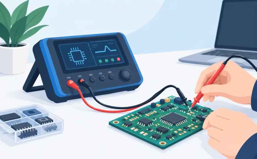
For surface-mount work, tweezer-style LCR instruments provide direct contact to component terminals without conventional probes slipping across adjacent pads. This improves speed when checking resistors, capacitors, inductors, and LEDs on densely populated assemblies. Siborg Systems instruments such as Smart Tweezers® are designed around this direct-access workflow, with models providing high basic accuracy, test frequencies up to 250 kHz, and configurations for portable or Bluetooth-connected measurement.

Oscilloscope for Powered-Circuit Behavior

A component can measure correctly unpowered and still fail under operating voltage, frequency, temperature, or load. An oscilloscope is the diagnostic tool for these cases. It shows whether a regulator is starting correctly, whether a clock is present, whether a PWM controller is switching, and whether an analog signal is clipping, oscillating, or carrying excessive noise.

Probe grounding and bandwidth deserve attention. A long ground lead can add inductance and display ringing that is not actually present at the circuit node. For fast switching signals, use the shortest practical ground connection and confirm that the probe and oscilloscope bandwidth are appropriate for the edge rate being observed. If the expected waveform is not known, compare with a known-good board whenever possible.

Analog Signature Analysis for Unpowered Comparison

Analog Signature Analysis, or ASA, applies a controlled AC stimulus to an unpowered circuit and displays its voltage-current response. The resulting signature can be compared between similar nodes, channels, or a known-good board. This method is useful when a board cannot be powered safely or when the fault may involve semiconductors, protection devices, or parallel component networks that are difficult to interpret with a simple resistance reading.

ASA does not identify every failed part automatically. Its value is comparative: a signature that differs materially from an equivalent circuit location indicates where further investigation should focus. It is especially effective on repeated channels, multi-output devices, and assemblies where a working reference board is available.

Why In-Circuit Measurements Need Context

The speed advantage of PCB diagnostic tools comes from testing parts without desoldering them first. The trade-off is that adjacent components and IC inputs can affect the reading. A resistor may be shunted by another path. A capacitor may be measured in parallel with several decoupling capacitors. An inductor may be part of a switching regulator path that changes the apparent result.

Use in-circuit values for screening and comparison. If a reading is clearly abnormal relative to the schematic, a matching circuit channel, or a known-good board, it is actionable. If the result is borderline, inconsistent, or physically implausible, isolate one terminal or remove the component before making a final decision. Replacing a part based on an ambiguous in-circuit reading can introduce a second fault and obscure the original one.

Component package size also affects practical accuracy. On 0201 and 0402 devices, probe pressure, oxide contamination, solder geometry, and hand stability can influence contact resistance. Fine tweezer tips, clean contacts, and a stable hand position often matter as much as the instrument specification.

A Faster Diagnostic Sequence

An efficient workflow narrows the fault domain before attempting detailed component analysis. Begin by documenting the reported symptom and checking the assembly for mechanical damage. With power off, measure resistance from each major supply rail to ground and compare suspicious rails with a known-good board or expected values.

Next, apply power through a controlled current-limited source when appropriate. Verify input voltage, regulator outputs, current draw, and temperature rise. A thermal anomaly can point to a shorted capacitor, failed IC, or improperly biased transistor, but it should be confirmed with electrical measurements before parts are removed.

Once the faulty section is identified, use the instrument suited to the component class. Check passive networks with LCR and ESR measurement, diodes and transistors with diode mode or component test, and active behavior with an oscilloscope. Use analog signature comparison when the board must remain unpowered or when equivalent channels are available.

Record values rather than relying on memory. Measurements captured through Bluetooth or transferred to a PC can support repair records, incoming inspection, failure analysis, and comparison across multiple units. For quality-controlled environments, calibration status matters as well. A NIST-traceable calibration certificate provides documented confidence that an instrument’s readings can support formal test and repair processes.

Selecting Tools by Board Type

There is no single best configuration for every application. A repair technician working on consumer electronics may prioritize fast SMD access, capacitance, ESR, and diode testing. A field technician servicing industrial controls may need rugged portability, reliable continuity testing, and the ability to evaluate power supplies quickly. A design engineer debugging switching converters or RF-adjacent circuits will place more weight on test frequency, waveform visibility, and repeatable data capture.

Higher test frequency is not automatically better. It is valuable when it reflects the component behavior or circuit conditions being investigated. Likewise, very high accuracy is useful only when probe contact, test setup, and in-circuit topology support that level of confidence. Select the instrument around the decisions it must support, not a specification list viewed in isolation.

The best diagnostic habit is simple: establish the failure mode, choose the measurement that can disprove your first assumption, and compare results against a valid reference. That approach turns a compact test instrument into a practical fault-isolation system, one component and one verified measurement at a time.

How to Test PCB Diodes Without Removing Them

A diode that reads 0.62 V in one direction and open in the other may be healthy – or it may be sharing a path with an IC, capacitor, or protection network. To test PCB diodes reliably, the measurement must be interpreted in the context of the circuit, not simply compared with a single expected number. This is especially true on compact boards, where SMD diodes are often connected directly to power rails and high-pin-count devices.

Start With a Safe, Repeatable Test Setup

Remove all power from the board before probing a diode. Disconnect batteries, adapters, USB power, and any external test equipment that could energize a rail. Then discharge large capacitors through an appropriate resistance path and verify that stored voltage is gone. A charged capacitor can affect the reading, damage a meter input, or create a false indication of diode conduction.

Identify the diode reference designator and determine its function before measuring. A series diode, flyback diode, ESD suppressor, rectifier, Schottky clamp, and Zener diode can all produce different readings under the same meter test mode. Board markings, the schematic, PCB layout, and the component package code are useful, but package codes alone are not definitive because many SMD devices share similar markings.

Good probe contact matters. Oxidized pads, conformal coating, and crowded components can turn a valid test into an intermittent one. Fine-point probes or tweezer-style contacts provide better access than standard multimeter leads when the pads are small and closely spaced. Keep the probes stable rather than scraping across the board, particularly around fine-pitch IC pins.

Use Diode Mode Before Resistance Mode

A digital multimeter’s diode mode applies a controlled test current and displays the resulting forward voltage. It is usually the fastest first test because it evaluates the junction rather than merely reporting a resistance value that can vary with meter range and test voltage.

Place the positive probe on the anode and the negative probe on the cathode. The cathode is commonly marked by a band on through-hole diodes and by a line or bar on many SMD packages. A conventional silicon diode often reads approximately 0.45 V to 0.80 V in the forward direction. A Schottky diode commonly reads lower, often around 0.15 V to 0.45 V, although current rating, temperature, and meter test current all affect the result.

Reverse the probes. A healthy isolated diode should normally display OL, open, or a reading substantially different from the forward result. The exact display depends on the instrument. Some meters show an overload indication; others show a value outside their diode-test range.

Resistance mode can be a useful secondary check, but it should not replace diode mode. A resistance measurement is influenced by the meter’s applied voltage and polarity. A diode may appear to have a moderate resistance in one meter range and a much higher resistance in another without indicating a fault.

What common readings usually mean

A forward reading near zero in both directions often indicates a shorted diode, but first rule out a parallel low-resistance path on the PCB. A diode that reads open in both directions may be open, improperly contacted, or connected to a circuit node that prevents the meter from applying enough voltage to forward-bias it.

A normal forward reading with a reverse open indication is encouraging, but it is not complete proof of a healthy part in circuit. The diode may still have excessive reverse leakage at its rated voltage, altered switching behavior, or a breakdown characteristic outside the range of the handheld meter.

When a measurement is suspicious, compare it with an identical diode channel or a known-good board. Comparative troubleshooting is often faster than searching for a universal voltage-drop specification, particularly in multi-channel power supplies, LED drivers, and protection circuits.

Why In-Circuit Diode Tests Can Mislead

The surrounding circuit determines what the meter sees. Parallel resistors can create an apparent conduction path in reverse direction. Semiconductor junctions inside MOSFETs, transistors, and ICs can look like additional diodes. Capacitors may charge from the meter’s test current, causing a reading that rises and then becomes open.

Power-rail connections are a frequent source of confusion. A TVS diode or ESD protection diode tied between a signal line and ground may show a forward junction reading in one probe direction, while the reverse direction may appear conductive through another IC input clamp. That does not automatically mean the protection diode has failed.

Watch the display for several seconds rather than recording the first value. A stable reading is more meaningful than one that changes quickly. If the displayed voltage climbs steadily, the meter may be charging a capacitor. If it falls after an initially open result, another semiconductor path may be turning on under the meter’s test conditions.

For a questionable result, isolate the diode by lifting one lead or removing the component. With two-terminal SMD parts, lifting one end is usually sufficient. This breaks parallel paths while avoiding unnecessary rework on the entire device. On multilayer boards, choose the end that is easiest to access and least likely to lift a fragile pad.

Test PCB Diodes by Device Type

Standard and switching diodes

For small-signal silicon and fast switching diodes, diode mode generally provides a useful pass-fail screen. Confirm a plausible forward drop and a high reverse reading. Do not assume that a slightly different forward voltage proves failure. Two nominally identical diodes can differ because of temperature, current level, and manufacturer process.

Schottky rectifiers

Schottky diodes have a lower forward drop and usually higher reverse leakage than silicon PN diodes. A low forward reading is expected. What matters is whether the reading is consistent with the circuit’s equivalent channel or known-good board, and whether the device is creating an abnormal short across a supply rail.

LEDs

Many multimeters can illuminate low-current red, green, or yellow LEDs in diode mode. White, blue, ultraviolet, and series-connected LEDs often require more voltage than the meter can provide. An OL reading on these devices does not necessarily indicate an open LED. Use a controlled LED tester or current-limited supply when the meter’s diode-test voltage is insufficient.

Zener and TVS diodes

Diode mode confirms the forward PN junction of a Zener or unidirectional TVS device, but it usually cannot verify reverse breakdown. Proper reverse testing requires a controlled supply, a series resistor, and a measurement of voltage at a specified current. For TVS parts, compare the measured behavior with the part’s standoff and breakdown specifications. Applying an uncontrolled supply directly across the device is not a valid test and can destroy a small SMD part.

Bidirectional TVS devices do not behave like a single ordinary diode in a basic diode-mode check. Their test result should be evaluated as a suppressor network, not as a simple anode-to-cathode junction.

Choose the Instrument for the Fault You Need to Find

A DMM is sufficient for rapid forward-drop and short-circuit checks. For dense assemblies, a compact tweezer-style instrument improves placement accuracy and can reduce time spent chasing poor probe contact. Siborg’s Smart Tweezers approach is designed for direct access to small SMD terminals, which is valuable when component spacing makes conventional probes unstable.

However, diode testing and LCR measurement answer different questions. A high-frequency LCR measurement is useful for identifying capacitors, inductors, and resistors and for detecting altered passive-component behavior, but it does not substitute for a diode’s forward and reverse characterization. Use the mode and test conditions that match the suspected failure.

Analog Signature Analysis, where available, can add context when an in-circuit reading is ambiguous. Comparing a suspect node’s current-voltage signature against the same node on a known-good board can reveal a short, open path, or altered clamp behavior without immediately removing parts. It is a comparative diagnostic method, not a replacement for confirming a diode’s rated reverse-voltage and leakage specifications.

Record Conditions, Not Just Results

For repair documentation and quality control, record the diode designation, board condition, probe polarity, test mode, reading, and whether the measurement was taken in circuit or with one terminal lifted. Include the meter model when a result is close to a decision limit. Different instruments use different diode-test currents and maximum test voltages, so a reading from one meter may not be directly comparable to another.

The most useful diode test is the one that answers a specific fault question. If a rail is shorted, look for near-zero conduction and compare related rails. If an LED string is dark, verify whether the tester can supply adequate forward voltage. If a Zener clamp is suspected, test it at a controlled reverse current. Careful test conditions turn a quick diode-mode reading into evidence you can trust.

Guide to Printed Circuit Troubleshooting

A board that is completely dead and a board that fails only after twenty minutes demand different evidence. The fastest technicians do not begin by replacing the most suspicious-looking part. They use a guide to printed circuit troubleshooting that narrows the fault from board level to circuit block, then to a component or interconnect that can be measured and verified.

The goal is not simply to find a bad component. It is to identify the failure mechanism: an open connection, a shorted rail, a leaky capacitor, a damaged semiconductor junction, a marginal solder joint, or an incorrect signal condition. That distinction prevents repeat failures and avoids introducing new defects during rework.

Start With the Failure Condition

Record what the assembly is supposed to do and exactly how it fails. Note whether the issue is constant, intermittent, temperature-dependent, load-dependent, or associated with a particular operating mode. A board that passes without load but collapses when a motor, RF stage, or display turns on often has a power-integrity issue rather than a logic fault.

Establish known-good reference conditions before probing. Confirm the correct input supply, polarity, current limit, connectors, firmware revision, and external fixtures. If a working board is available, it is one of the most useful diagnostic references. Comparing voltage, resistance, impedance, waveform shape, and component values against a known-good unit can reduce troubleshooting time substantially.

For intermittent failures, document the trigger. Flexing a PCB, applying controlled heat, cooling a localized area, or changing supply voltage can expose cracked solder joints, weak vias, and marginal components. Use these methods carefully. Thermal stress can create temporary changes that obscure the original failure if it is applied indiscriminately.

Guide to Printed Circuit Troubleshooting: Inspect First

Perform a deliberate visual inspection under adequate magnification before applying power. Look for missing parts, wrong orientation, solder bridges, lifted pads, insufficient solder fillets, damaged vias, contaminated areas, and connector wear. Darkened laminate, discolored resistors, cracked MLCCs, or residue around electrolytic capacitors may indicate the fault, but appearance alone is not proof.

Pay particular attention to component polarity and package markings. Reversed diodes, polarized capacitors, LEDs, ICs, and transistor packages are common causes of immediate malfunction after assembly or repair. On dense boards, verify pin-one orientation against the PCB designator and package datasheet rather than relying on visual assumptions.

Also inspect mechanically stressed locations: board-edge connectors, heavy inductors, large capacitors, heat-sinked devices, switches, and areas near mounting holes. Repeated vibration or connector insertion can fracture solder joints or barrel plating while leaving the exterior of the joint apparently intact.

Make Power Rails Safe and Measurable

Before energizing a suspect board, measure resistance from each supply rail to ground. A very low resistance is not automatically a fault. High-current digital rails, processor cores, and power stages can normally measure below a few ohms. What matters is whether the reading is consistent with the design, the rail topology, and a known-good board.

Use a current-limited bench supply whenever practical. Begin at the specified voltage with a conservative current limit, then observe the current draw. A supply that immediately enters current limiting indicates a short, reverse-polarity condition, failed power semiconductor, or incorrect assembly. A board drawing almost no current may have an open fuse, connector problem, disabled regulator, or broken trace.

Check the power chain in order: input protection, fuse or zero-ohm link, reverse-polarity device, switching or linear regulator, local rail filters, and load rails. Measure at both sides of series elements. A correct voltage at a regulator input does not establish that the output is stable, correctly sequenced, or capable of supplying load current.

An oscilloscope is particularly useful at switching-regulator outputs. Excessive ripple, burst cycling, repeated startup attempts, or high-frequency ringing can identify overload, bad compensation, failed feedback components, or degraded output capacitors. A DC multimeter reading can appear normal while the rail is unstable enough to reset digital circuitry.

Separate Shorts, Opens, and Leakage

A short is usually easier to locate than leakage, but both can produce similar symptoms. For a suspected shorted rail, inject a controlled low voltage with an appropriate current limit and search for localized heating. Thermal imaging is effective, but alcohol evaporation, freeze spray, or careful fingertip checks can help where appropriate. Never use a voltage that can forward-bias or damage downstream ICs.

For opens, continuity mode is useful only when interpreted correctly. Test across fuses, links, traces, vias, connector pins, and solder joints while accounting for parallel paths. A continuity beep does not guarantee a low-resistance, reliable connection under operating current. Milliohm-level resistance across a stressed path may matter in high-current circuits.

Leakage faults demand more care. Contamination, moisture, damaged protection devices, and leaky semiconductors can pull a high-impedance node away from its intended voltage without appearing as a hard short. Compare resistance readings in both polarities, inspect the area for flux residue, and measure the node during operation. Cleaning may be corrective, but it should not replace finding the contamination source.

Test Components in Circuit With Context

In-circuit measurement is fast, but parallel components affect the result. A resistor in parallel with another path reads lower than its marked value. A capacitor on a supply rail may be measured alongside dozens of other capacitors. An inductor can be shunted by semiconductor paths. Use the schematic, board layout, and surrounding topology to decide whether an in-circuit result is conclusive.

For small SMD components, tweezer-style LCR measurement provides direct access without chasing test leads across adjacent pads. Measure resistance, capacitance, inductance, and impedance as appropriate to the circuit. Test frequency matters: a value measured at a low frequency may not reveal behavior relevant to a switching converter, RF filter, or high-speed control loop.

ESR testing is valuable for capacitors in power and analog sections. A capacitor can retain a plausible capacitance value while its ESR has risen enough to produce ripple, instability, startup failure, or poor transient response. Compare capacitors of the same type and location when a known-good board is available. Do not condemn every capacitor with a nonideal in-circuit reading, especially when it is paralleled by other parts.

Diode mode is effective for checking protection diodes, rectifiers, LEDs, transistor junctions, and many IC input structures. Compare forward voltage and reverse behavior between equivalent channels or a reference board. A zero reading in both directions may indicate a short, while an open reading in both directions may be normal for the circuit or may indicate a broken connection. Circuit context decides the result.

Siborg Smart Tweezers and LCR-Reader instruments are designed for this work because the probes contact small components directly while displaying key parameters quickly. Higher-frequency LCR testing, up to 250 kHz on applicable instruments, is useful when component behavior at operating-relevant frequencies matters more than a nominal low-frequency value.

Follow the Signal Path, Not Random Test Points

Once power is confirmed, divide the circuit into functional blocks: input conditioning, reference generation, controller, driver, output stage, communications interface, or sensor front end. Identify where the expected signal enters and exits each block. This creates a sequence of meaningful measurements instead of an unstructured search.

Use a scope for timing, clock presence, reset behavior, PWM activity, data traffic, and analog signal integrity. Check amplitude, offset, frequency, duty cycle, rise time, and noise against the design expectation. A clock may be present but too low in amplitude. A reset line may release briefly and then assert because a supply rail dips. These faults are missed when only static voltage is measured.

Analog Signature Analysis can help compare a suspect node or component with a known-good signature while the board is unpowered. It is useful for identifying altered semiconductor junctions, opens, shorts, and unexpected parallel paths. Like any comparative technique, it is strongest when equivalent nodes can be tested under the same conditions.

Verify the Repair Under Real Conditions

After replacing a part or correcting an interconnect, repeat the original failure test. Confirm that the board reaches normal current draw, all regulated rails remain stable, and the intended function operates through its full duty cycle. A repair that passes at room temperature on the bench may still fail under load, vibration, or thermal stress.

Inspect the rework area under magnification. Confirm pad integrity, solder wetting, component orientation, clearance to adjacent pads, and removal of conductive debris. For production or regulated work, record the failed condition, measurements, corrective action, replacement component identification, and final verification result.

The most useful measurement is the one that eliminates a branch of the fault tree. Work from the board’s known conditions toward its unknowns, preserve evidence before rework, and let the circuit topology determine the next probe point.