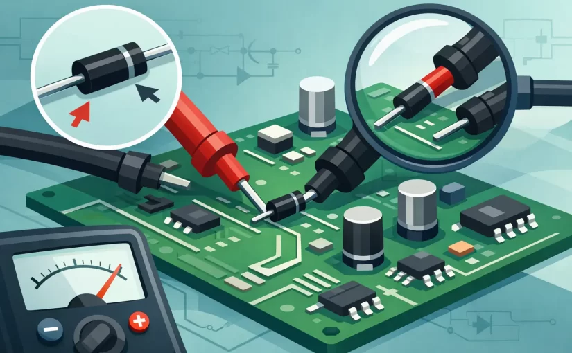
A diode that reads 0.62 V in one direction and open in the other may be healthy – or it may be sharing a path with an IC, capacitor, or protection network. To test PCB diodes reliably, the measurement must be interpreted in the context of the circuit, not simply compared with a single expected number. This is especially true on compact boards, where SMD diodes are often connected directly to power rails and high-pin-count devices.
Start With a Safe, Repeatable Test Setup
Remove all power from the board before probing a diode. Disconnect batteries, adapters, USB power, and any external test equipment that could energize a rail. Then discharge large capacitors through an appropriate resistance path and verify that stored voltage is gone. A charged capacitor can affect the reading, damage a meter input, or create a false indication of diode conduction.
Identify the diode reference designator and determine its function before measuring. A series diode, flyback diode, ESD suppressor, rectifier, Schottky clamp, and Zener diode can all produce different readings under the same meter test mode. Board markings, the schematic, PCB layout, and the component package code are useful, but package codes alone are not definitive because many SMD devices share similar markings.
Good probe contact matters. Oxidized pads, conformal coating, and crowded components can turn a valid test into an intermittent one. Fine-point probes or tweezer-style contacts provide better access than standard multimeter leads when the pads are small and closely spaced. Keep the probes stable rather than scraping across the board, particularly around fine-pitch IC pins.
Use Diode Mode Before Resistance Mode
A digital multimeter’s diode mode applies a controlled test current and displays the resulting forward voltage. It is usually the fastest first test because it evaluates the junction rather than merely reporting a resistance value that can vary with meter range and test voltage.
Place the positive probe on the anode and the negative probe on the cathode. The cathode is commonly marked by a band on through-hole diodes and by a line or bar on many SMD packages. A conventional silicon diode often reads approximately 0.45 V to 0.80 V in the forward direction. A Schottky diode commonly reads lower, often around 0.15 V to 0.45 V, although current rating, temperature, and meter test current all affect the result.
Reverse the probes. A healthy isolated diode should normally display OL, open, or a reading substantially different from the forward result. The exact display depends on the instrument. Some meters show an overload indication; others show a value outside their diode-test range.
Resistance mode can be a useful secondary check, but it should not replace diode mode. A resistance measurement is influenced by the meter’s applied voltage and polarity. A diode may appear to have a moderate resistance in one meter range and a much higher resistance in another without indicating a fault.
What common readings usually mean
A forward reading near zero in both directions often indicates a shorted diode, but first rule out a parallel low-resistance path on the PCB. A diode that reads open in both directions may be open, improperly contacted, or connected to a circuit node that prevents the meter from applying enough voltage to forward-bias it.
A normal forward reading with a reverse open indication is encouraging, but it is not complete proof of a healthy part in circuit. The diode may still have excessive reverse leakage at its rated voltage, altered switching behavior, or a breakdown characteristic outside the range of the handheld meter.
When a measurement is suspicious, compare it with an identical diode channel or a known-good board. Comparative troubleshooting is often faster than searching for a universal voltage-drop specification, particularly in multi-channel power supplies, LED drivers, and protection circuits.
Why In-Circuit Diode Tests Can Mislead
The surrounding circuit determines what the meter sees. Parallel resistors can create an apparent conduction path in reverse direction. Semiconductor junctions inside MOSFETs, transistors, and ICs can look like additional diodes. Capacitors may charge from the meter’s test current, causing a reading that rises and then becomes open.
Power-rail connections are a frequent source of confusion. A TVS diode or ESD protection diode tied between a signal line and ground may show a forward junction reading in one probe direction, while the reverse direction may appear conductive through another IC input clamp. That does not automatically mean the protection diode has failed.
Watch the display for several seconds rather than recording the first value. A stable reading is more meaningful than one that changes quickly. If the displayed voltage climbs steadily, the meter may be charging a capacitor. If it falls after an initially open result, another semiconductor path may be turning on under the meter’s test conditions.
For a questionable result, isolate the diode by lifting one lead or removing the component. With two-terminal SMD parts, lifting one end is usually sufficient. This breaks parallel paths while avoiding unnecessary rework on the entire device. On multilayer boards, choose the end that is easiest to access and least likely to lift a fragile pad.
Test PCB Diodes by Device Type
Standard and switching diodes
For small-signal silicon and fast switching diodes, diode mode generally provides a useful pass-fail screen. Confirm a plausible forward drop and a high reverse reading. Do not assume that a slightly different forward voltage proves failure. Two nominally identical diodes can differ because of temperature, current level, and manufacturer process.
Schottky rectifiers
Schottky diodes have a lower forward drop and usually higher reverse leakage than silicon PN diodes. A low forward reading is expected. What matters is whether the reading is consistent with the circuit’s equivalent channel or known-good board, and whether the device is creating an abnormal short across a supply rail.
LEDs
Many multimeters can illuminate low-current red, green, or yellow LEDs in diode mode. White, blue, ultraviolet, and series-connected LEDs often require more voltage than the meter can provide. An OL reading on these devices does not necessarily indicate an open LED. Use a controlled LED tester or current-limited supply when the meter’s diode-test voltage is insufficient.
Zener and TVS diodes
Diode mode confirms the forward PN junction of a Zener or unidirectional TVS device, but it usually cannot verify reverse breakdown. Proper reverse testing requires a controlled supply, a series resistor, and a measurement of voltage at a specified current. For TVS parts, compare the measured behavior with the part’s standoff and breakdown specifications. Applying an uncontrolled supply directly across the device is not a valid test and can destroy a small SMD part.
Bidirectional TVS devices do not behave like a single ordinary diode in a basic diode-mode check. Their test result should be evaluated as a suppressor network, not as a simple anode-to-cathode junction.
Choose the Instrument for the Fault You Need to Find
A DMM is sufficient for rapid forward-drop and short-circuit checks. For dense assemblies, a compact tweezer-style instrument improves placement accuracy and can reduce time spent chasing poor probe contact. Siborg’s Smart Tweezers approach is designed for direct access to small SMD terminals, which is valuable when component spacing makes conventional probes unstable.
However, diode testing and LCR measurement answer different questions. A high-frequency LCR measurement is useful for identifying capacitors, inductors, and resistors and for detecting altered passive-component behavior, but it does not substitute for a diode’s forward and reverse characterization. Use the mode and test conditions that match the suspected failure.
Analog Signature Analysis, where available, can add context when an in-circuit reading is ambiguous. Comparing a suspect node’s current-voltage signature against the same node on a known-good board can reveal a short, open path, or altered clamp behavior without immediately removing parts. It is a comparative diagnostic method, not a replacement for confirming a diode’s rated reverse-voltage and leakage specifications.
Record Conditions, Not Just Results
For repair documentation and quality control, record the diode designation, board condition, probe polarity, test mode, reading, and whether the measurement was taken in circuit or with one terminal lifted. Include the meter model when a result is close to a decision limit. Different instruments use different diode-test currents and maximum test voltages, so a reading from one meter may not be directly comparable to another.
The most useful diode test is the one that answers a specific fault question. If a rail is shorted, look for near-zero conduction and compare related rails. If an LED string is dark, verify whether the tester can supply adequate forward voltage. If a Zener clamp is suspected, test it at a controlled reverse current. Careful test conditions turn a quick diode-mode reading into evidence you can trust.