PCB Inspection Accessories for Accurate Testing

A board can pass visual inspection and still fail at a single 0402 capacitor, cracked solder joint, or leakage path. The right PCB inspection accessories determine whether a technician reaches the actual node or damages the evidence while trying. For component-level troubleshooting, accessories are not secondary purchases. They are the mechanical and electrical interface between a precision instrument and a densely populated assembly.

What PCB Inspection Accessories Must Do

A useful accessory has two jobs: establish repeatable electrical contact and preserve the board under test. Those requirements often conflict. A sharp probe can penetrate oxidation and reach a small test point, but it can also slip, tear solder mask, or bridge adjacent pads. A larger contact offers stability but may be too wide for fine-pitch work.

The correct choice depends on the measurement, component package, board condition, and whether the assembly is powered. Measuring a loose resistor permits a different setup than checking an in-circuit MLCC beside a QFN. A field technician working on a conformal-coated control board also faces different access limits than a production operator verifying assemblies on a fixture.

Accessories should support the capability of the meter rather than become the limiting factor. For example, a precision LCR measurement at 100 kHz or 250 kHz needs clean, low-resistance contact and short current paths. Poor probe placement can add unstable contact resistance, parasitic capacitance, and inductance that obscure the component value being investigated.

Tweezer Tips for Direct SMD Access

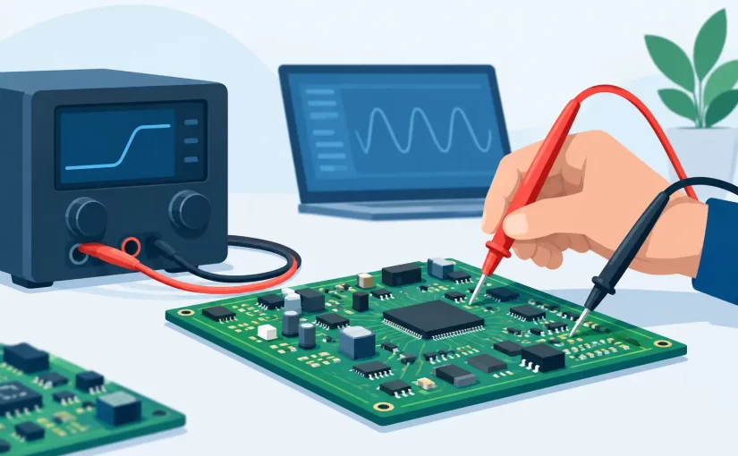
Tweezer-style probes are among the most practical PCB inspection accessories for surface-mount work. Their two contacts can approach both ends of a chip resistor, capacitor, diode, or LED without requiring separate hands to position conventional test leads. This improves speed, but more importantly, it improves placement control.

Fine gold-plated tips are appropriate when the target is a small chip component or closely spaced pads. Gold plating resists oxidation and provides consistent low-force contact. Replaceable tips also matter in repair environments because worn or bent points change both access and measurement repeatability.

Tip geometry should match the work. Needle points reach narrow component terminations and vias, while flattened or rounded tips distribute force across more of the pad. For delicate multilayer boards, use the lightest pressure that produces a stable reading. Excessive force can crack a ceramic capacitor, lift a pad, or create intermittent contact that looks like a defective part.

Insulated or closely controlled tweezer arms reduce the chance of bridging nearby conductors. This is particularly valuable around fine-pitch ICs, dense power-management sections, and assemblies carrying residual charge. Before probing, discharge high-voltage capacitors and verify the board is safe for the selected instrument mode.

Siborg Smart Tweezers and LCR-Reader instruments are designed around this direct-contact approach, allowing users to identify and measure many SMD components without removing them from the board. The result is faster isolation of suspect parts when circuit conditions allow an in-circuit reading.

When In-Circuit Readings Need Confirmation

No probe accessory can remove the influence of parallel paths. A capacitor measured on a populated board may appear larger because other capacitance is connected across the same nodes. A resistor can read lower because of parallel circuitry. Semiconductor junctions and energized sections may create readings that do not represent the individual device.

Use the first reading as diagnostic evidence, not automatic proof. Compare with a known-good channel, an identical board location, or the schematic expectation. If the value remains questionable, isolate one end of the component or remove it for confirmation. Good accessories make that decision faster by giving a stable initial measurement.

Probe Leads, Hooks, and Clips for Circuit Nodes

Tweezer probes excel at two-terminal components, but board-level investigation also requires access to rails, test points, connector pins, and timing signals. Flexible silicone test leads are preferable for bench work because they remain manageable near heat and do not pull lightweight probes off the target. Low-profile, shrouded connectors help maintain safe and consistent instrument connections.

Hook clips are useful for temporary attachment to test loops, wire leads, and larger component terminals. They free the operator to adjust settings, compare channels, or record readings. Their limitation is physical size: a hook clip is unsuitable for crowded SMD areas and can stress fragile solder joints if the lead is unsupported.

For oscilloscope or Analog Signature Analysis work, use probes with the bandwidth, attenuation, and grounding arrangement appropriate to the signal. A long ground lead can introduce ringing and distort a fast edge. For low-level or higher-frequency observations, keep the probe ground connection short and close to the measurement point. This is not a cosmetic setup detail. Ground-loop inductance can make a healthy switching waveform look defective.

Fine needle probes remain useful when a circuit has exposed vias, test pads, or solder joints that cannot be reached with clips. Choose insulated handles and tips that can be replaced when worn. A dull tip requires more pressure, and more pressure increases the risk of slipping across adjacent copper.

PCB Holders, Lighting, and Magnification

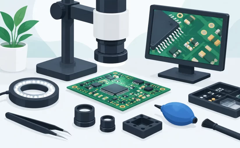
Electrical contact is only part of inspection. A board that moves under a probe compromises the measurement and raises the chance of damage. An adjustable PCB holder stabilizes the assembly, keeps both hands available, and allows the board to be positioned at a useful angle. Nonmarring jaws are preferred for boards with edge connectors, sensitive coatings, or finished panels.

Magnification and directed lighting help distinguish a component fault from an assembly defect. Under adequate illumination, technicians can identify tombstoned passives, incomplete solder fillets, solder bridges, lifted pads, polarized-part orientation errors, and corrosion around connectors. A magnifier lamp may be sufficient for general repair; a stereo microscope is more appropriate for fine-pitch packages and rework verification.

Lighting should be adjustable rather than simply bright. Low-angle illumination reveals raised leads and uneven solder joints through shadows, while diffuse light reduces glare from flux residue and conformal coating. If inspection includes photography or documentation, use stable, repeatable lighting so images can be compared across boards and shifts.

Cleaning and Protection Accessories

Contamination changes both visual inspection and electrical measurement. Flux residue, moisture, corrosion products, and fingerprints can create leakage paths, especially in high-impedance circuits. Before diagnosing an unusual resistance or insulation-related issue, inspect and clean the relevant area using materials compatible with the assembly and its coating.

ESD controls are equally practical. A grounded work mat and wrist strap protect sensitive devices during open-board inspection. They also create a defined workspace where small SMD components, spare tips, and adapters are less likely to be lost. For boards outside an ESD-controlled environment, use antistatic trays or bags during transport and staging.

Probe tip covers, instrument cases, and organized accessory storage deserve attention as well. A precision meter cannot retain dependable field performance if its contacts are bent in a tool bag or contaminated by loose hardware. Store tips separately from abrasive tools and replace damaged leads before they become a source of intermittent readings.

Selecting Accessories by Measurement Task

Start with the fault class, then select the contact method. For SMD value verification, fine tweezer tips and a capable LCR or ESR meter provide the most direct workflow. For rail checks and continuity tracing, flexible leads with needle probes or hook clips are usually more suitable. For waveform investigation, use the correct oscilloscope probe and the shortest practical ground connection.

A practical accessory set for a technician handling varied PCB work should cover five distinct needs:

  • Fine replaceable tweezer tips for chip components and small pads.
  • Insulated needle probes for vias, test points, and solder joints.
  • Hook clips for hands-free connection to larger terminals and loops.
  • A stable PCB holder with nonmarring board support.
  • ESD, cleaning, lighting, and magnification tools for safe visual and electrical inspection.

Do not select solely by tip sharpness or lead length. Consider the voltage category, insulation condition, connector compatibility, mechanical strain on the board, and the instrument’s specified measurement range. Accessories used with energized circuits must be rated for the environment and handled under established safety procedures.

Repeatability Is the Real Performance Test

A single reading can be misleading. Repeatable readings obtained with controlled contact pressure, clean tips, and stable board support are far more useful. If the displayed value shifts each time the probe is repositioned, investigate the setup before declaring the component faulty.

Build a simple bench routine: inspect the target under magnification, stabilize the board, choose the smallest safe contact geometry, make the measurement, and compare it with a reference when possible. For documented repair, record the instrument mode, test frequency, and probe location along with the value. Bluetooth-enabled instruments can further reduce transcription errors when measurements need to be transferred to a mobile device or PC.

The best PCB inspection accessories do not merely add reach. They make each contact deliberate, each result easier to trust, and each troubleshooting decision easier to defend.
How to Calibrate Handheld Multimeters Correctly

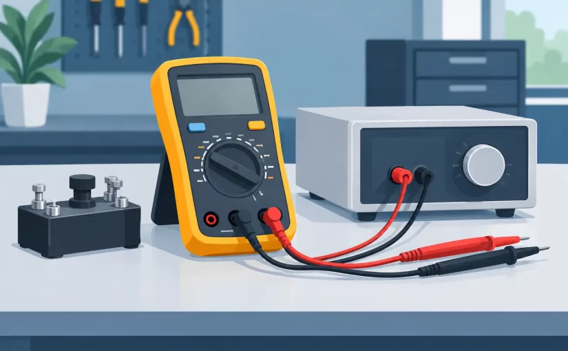
A handheld multimeter that reads 4.98 V when the circuit is known to be 5.00 V is not necessarily defective. But if that error exceeds the meter’s stated accuracy, shifts between ranges, or appears after an overload event, the instrument needs attention. Knowing how to calibrate handheld multimeters means separating a quick performance verification from an actual adjustment, then documenting results that can support engineering, production, or service decisions.

For most professional handheld meters, calibration is not a matter of turning an internal trimmer until the display looks right. Modern meters commonly use protected calibration modes, stored coefficients, reference sources, and manufacturer-specific procedures. The right process depends on the required uncertainty, the functions being verified, and whether the meter must maintain traceable calibration status.

Calibration, Verification, and Adjustment Are Different Tasks

A calibration compares meter readings against known standards and records the error at specified test points. It does not automatically include an adjustment. Verification is a narrower check that confirms whether readings remain within an acceptance limit. Adjustment changes the meter’s internal calibration constants or circuitry to reduce error.

This distinction matters in a repair department or quality system. A meter can pass calibration even when it does not display the exact nominal value of every applied standard. Its reading only needs to fall within the applicable specification and measurement uncertainty. Conversely, changing calibration data without first documenting the as-found condition removes useful evidence about drift, damage, or misuse.

For a meter used to troubleshoot low-voltage electronics, a basic voltage and resistance verification may be sufficient between formal calibration intervals. For production acceptance testing, safety-critical field work, or measurements used in compliance records, use a documented calibration procedure and traceable standards. A NIST-traceable certificate establishes the reference chain, but it does not by itself guarantee that a particular measurement setup is free of lead, contact, temperature, or operator error.

What You Need to Calibrate a Handheld Multimeter

The reference equipment must be more accurate than the device under test by a meaningful margin. A common target is a test uncertainty ratio of 4:1 or better, although the appropriate ratio depends on the quality system and the meter specification. Calibrating a 0.1% handheld meter with a reference that is only 0.2% accurate does not produce a defensible result.

At minimum, prepare a stable voltage reference or multifunction calibrator, precision resistance standards, quality low-thermal test leads, suitable adapters, and a record sheet or calibration software. AC voltage and current functions require standards that specify frequency, waveform quality, burden capability, and uncertainty. Capacitance, frequency, continuity, diode test, and temperature functions each require dedicated sources or simulators if they are included in the calibration scope.

Use standards with current calibration certificates and allow both the standards and meter to stabilize in the same environment. Most specifications are stated near 23 C, often with a limited temperature range and humidity condition. A meter brought in from a cold service vehicle can show temporary offset or gain changes. Allow at least 30 minutes of warm-up unless the manufacturer specifies otherwise.

Before connecting anything, inspect the meter. Check the case, rotary switch, input jacks, fuse ratings, battery condition, display, probe insulation, and lead resistance. Replace damaged leads rather than attempting to compensate for them in the results. For current ranges, confirm that the correct high-energy fuse is installed and that the input jack labeling is readable.

How to Calibrate Handheld Multimeters Step by Step

Start with the manufacturer’s service manual or calibration procedure. It defines required standards, test points, settling times, allowable errors, and whether adjustment is permitted. A user manual rarely contains enough information for a full calibration.

Establish the As-Found Condition

Record the meter model, serial number, firmware revision if available, environmental conditions, accessories used, and the date. Set the meter to its default configuration. Disable relative mode, peak capture, filtering, Bluetooth logging, and other functions that can affect the displayed value.

Apply each specified reference point and allow the reading to settle. Record the applied value, the displayed value, the calculated error, the allowable tolerance, and a pass or fail result. Cover the ranges that matter to the intended work, not just a convenient midscale DC voltage point.

For DC voltage, test zero or near zero, a low-range point, midrange, and a high-range point. For resistance, use standards that exercise the low-ohm range as well as higher ranges. Short the leads first to identify their contribution. On a 2-wire handheld meter, lead and contact resistance can dominate low-resistance measurements unless the meter has a relative function or the procedure accounts for the offset.

Verify DC Voltage and Resistance Carefully

Connect the voltage standard directly to the voltage input and common terminal. Select the required range manually when the procedure calls for it. Autoranging can be useful in normal troubleshooting, but fixed-range tests better identify range-specific errors.

Readings should be evaluated against the meter specification in the form commonly used by manufacturers: a percentage of reading plus counts. For example, an accuracy of ±(0.5% of reading + 2 counts) has two components. At 10.000 V on a meter with 1 mV resolution, the percentage component is 50 mV and the counts component is 2 mV, for a total allowable error of 52 mV. The exact calculation must use the selected range resolution, not an assumed display resolution.

For resistance, use clean connectors and avoid touching exposed terminals with your fingers. Body resistance and surface contamination can affect higher resistance values. If testing megohm ranges, use guarded fixtures or the manufacturer-recommended setup when available, and allow additional settling time.

Add AC, Current, and Specialized Functions Only When Supported

AC calibration is more demanding than DC calibration. Meter bandwidth, crest factor, true-RMS conversion, and signal amplitude all influence the result. Test the specified frequencies and amplitudes rather than assuming that a 60 Hz sine wave proves performance at 1 kHz or 10 kHz. A non-true-RMS meter may read accurately only for sine waves within its defined range.

Current ranges require particular care. A current calibrator or a suitable source with a precision shunt is preferable to improvised bench setups. Never move a lead from the voltage jack to the current jack while the source is energized. Verify the meter fuse before testing, and ensure the source can tolerate a momentary open circuit if the fuse operates.

Frequency, duty cycle, capacitance, diode, continuity, and temperature functions should be checked only with appropriate standards. A simple voltage reference cannot validate capacitance accuracy or diode-test current. For component-level diagnostics, a handheld multimeter also cannot replace an LCR meter or ESR meter where test frequency, AC stimulus, and equivalent-series-resistance resolution determine the result.

Compare Results and Decide Whether Adjustment Is Needed

If all results are within limits, retain the as-found data as the as-left data, apply the calibration status label if required, and set the next due date according to actual use and quality requirements. A yearly interval is common, but it is not universal. High-use field meters, instruments exposed to temperature cycling, and meters used for tighter tolerances may need more frequent verification.

If the meter fails, do not immediately adjust it. Check the battery, leads, input protection, range selection, reference setup, and environmental conditions. Repeat the failed point with a second standard if practical. A consistent failure may indicate genuine drift; an intermittent result may point to contaminated jacks, damaged leads, a weak battery, or switch-contact problems.

Adjustment should be performed only with the approved procedure, correct access method, and required standards. Many professional instruments store calibration constants in nonvolatile memory and may require a password, service software, or a controlled sequence. Unauthorized adjustment can invalidate prior records, compromise safety ratings, or make future traceability difficult.

Documentation Makes Calibration Useful

A useful calibration record identifies the standards used, their certificate numbers and due dates, the environmental conditions, test points, tolerances, actual readings, uncertainty statement where applicable, technician identity, and final status. Include repair actions and the post-adjustment results when adjustment was necessary.

For a lab managing several handheld instruments, trend the error over time. A meter that passes every year but drifts steadily toward one tolerance limit may warrant a shorter interval or preventative service. This is more informative than treating every calibration event as an isolated pass or fail.

Siborg Systems instruments are supplied for precision electronic measurement workflows, and calibration documentation should match the level of confidence required by the work. A quick bench check can protect a troubleshooting session; traceable calibration supports decisions that must stand up to audit, production review, or customer requirements.

When the reading affects a component decision, a repair release, or a safety measurement, treat calibration as measurement control rather than paperwork. The best result is not a display forced to match a nominal number, but a handheld meter with known error, verified performance, and records that make its measurements credible.

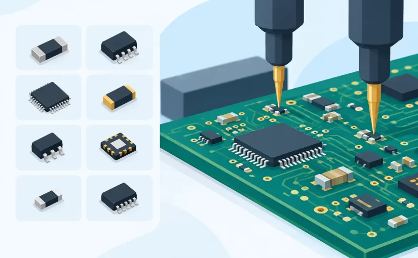
Surface Mount Package Guide for PCB Testing

A 0402 capacitor and a SOT-23 transistor can occupy only a few square millimeters, yet each can stop a board from operating correctly. A useful surface mount package guide is therefore more than a naming reference. It connects the package on the PCB to its pad geometry, thermal behavior, assembly risks, and the practical limits of in-circuit measurement.

For repair, inspection, and production work, package identification is the first decision point. It tells the operator where the terminals are, what nearby conductors may affect a reading, whether heat can safely be applied, and which probe or tweezer tip can make repeatable contact.

Why the Package Matters Before You Measure

A surface-mount device package defines the component’s physical interface to the board. The electrical function may be familiar – resistor, capacitor, diode, MOSFET, regulator, or integrated circuit – but the package determines how that function is accessed. A 0603 resistor has exposed end terminations that are easy to contact with fine test tweezers. A QFN has contacts beneath its body, making direct pin access more limited. A BGA hides nearly all solder joints under the package and changes the inspection process completely.

Package size also affects parasitics. At low frequencies, a nominal 10 nF capacitor may look similar whether it is housed in 0805 or 0201. At higher test frequencies, lead structure, termination geometry, dielectric construction, and mounting layout have a greater influence. The measured result may include the component, its solder joints, and parallel or series paths on the PCB.

This is why a component value alone is not enough for diagnosis. Identify the package, study its connections, then select a measurement method that matches the device and circuit conditions.

Common Surface-Mount Package Families

Chip resistors, capacitors, and inductors

Rectangular chip components are commonly designated by codes such as 1206, 0805, 0603, 0402, and 0201. In the imperial system, an 0603 package measures approximately 0.06 by 0.03 inches. Metric package designations are also used, so confirm the convention in a bill of materials or manufacturer drawing before ordering replacements.

These packages usually have two metallized end terminations. Their simple construction makes them suitable for direct two-terminal measurement, but circuit context still matters. A resistor can often be checked in circuit when no alternate current path is present. Capacitors and inductors are more likely to be affected by surrounding components, power planes, and semiconductor junctions.

Larger chip packages dissipate more heat and are generally easier to rework. Smaller packages reduce board area and can improve high-frequency layout, but their solder fillets are harder to inspect and their terminations demand accurate probe placement.

Diodes, transistors, and small-outline power devices

SOT-23, SOT-23-5, SOT-89, SOD-123, SOD-323, and SMA/SMB-style packages are common in switching, protection, and regulation circuits. Their terminal arrangement must be verified from the specific part documentation. Two devices in the same SOT-23 outline can have different pin assignments and entirely different functions.

For a diode or transistor, begin with the package orientation mark and locate pin 1 or the cathode marking. Then use diode-test or controlled LCR measurement as appropriate. In-circuit diode readings can be misleading when parallel diodes, IC inputs, or charged capacitors are present. Compare with a known-good channel or isolate one terminal when the circuit does not support a clear diagnosis.

SOIC, TSSOP, QFP, QFN, and DFN packages

Leaded IC packages such as SOIC, TSSOP, and QFP expose their gull-wing leads at the package perimeter. They can be visually inspected for bridges, lifted leads, insufficient solder, and corrosion. Fine-pitch spacing increases the chance that a conventional probe tip will contact adjacent pins, so probe geometry becomes a safety and accuracy issue.

QFN and DFN packages have pads underneath or partly underneath the body. They reduce inductance and package height, but center thermal pads and hidden side contacts complicate inspection. A failed QFN is often diagnosed through accessible decoupling capacitors, nearby resistors, exposed test points, or signal behavior rather than direct contact with every package terminal.

BGA and chip-scale packages

Ball grid arrays place solder balls beneath the package. They provide high I/O density and favorable electrical performance, especially for processors, memory, and high-speed devices. Their trade-off is accessibility: optical inspection cannot confirm every solder joint, and rework requires controlled heating, alignment, and usually X-ray or other specialized inspection methods.

At board level, BGA troubleshooting often starts with rail resistance, decoupling-capacitor measurements, clock and reset checks, and thermal observations. Package identification still guides the work, but the useful test points are often outside the device footprint.

Reading Markings, Orientation, and Footprints

Package markings are helpful but not always unique. A two- or three-character top mark may identify multiple devices from different manufacturers. Use it alongside package dimensions, pin count, board reference designator, circuit position, and surrounding components. The marking alone is rarely adequate evidence for replacement selection.

Orientation indicators deserve the same care. Dots, chamfered corners, molded dimples, laser marks, bars, and cathode bands may indicate pin 1 or polarity. On a board, the silkscreen may be incomplete, obscured by the part, or inconsistent with a revision change. Verify orientation from copper pads and the schematic when available.

The footprint is the PCB land pattern intended for the package. It establishes pad width, spacing, solder-mask clearance, paste aperture, and thermal connection. A part can be the correct nominal package yet be unsuitable if its terminal style or recommended land pattern differs. This occurs frequently with QFN thermal pads, diode packages, and chip capacitors from different vendors.

A Surface Mount Package Guide for Measurement Work

Measurement begins with safe board conditions. Remove power, discharge capacitors where necessary, and consider whether the circuit may contain battery-backed rails or charged high-voltage sections. Then inspect the component under magnification before placing probes. Cracked bodies, tombstoned chip components, solder voids, discolored terminations, and pad lifting can explain a failure before any numerical reading is taken.

For two-terminal components, clean contacts and correct tip pressure are central to repeatability. Excess pressure can slide an 0201 part, fracture a ceramic capacitor, or create intermittent contact. Too little pressure can add unstable resistance. Fine, gold-plated tweezer probes provide a controlled way to contact both terminations without shorting adjacent pads.

Test frequency should match the question being asked. A low-frequency capacitance measurement may confirm that a capacitor is not open or grossly shorted. Higher-frequency LCR and ESR measurements can better reveal behavior relevant to switching supplies, RF bypassing, and low-impedance ceramic capacitors. Results should be compared against the expected tolerance, package type, dielectric, and circuit topology – not merely the nominal printed value.

In-circuit readings require judgment. A resistor across an IC input may measure lower than its marked value because other paths are in parallel. A capacitor on a power rail may show a low apparent impedance because dozens of capacitors share the rail. If the reading is questionable, lift one end only when the board, component value, and repair economics justify it.

Compact instruments designed for SMD work reduce handling time because the operator can grip a loose component or contact installed end caps directly. Siborg Smart Tweezers and LCR-Reader instruments are intended for this workflow, with automatic component identification on supported models and measurement options suited to component-level PCB diagnosis. For controlled documentation, calibration status and measurement conditions should be recorded with the result.

Selecting a Replacement Package

A replacement must match more than capacitance, resistance, or semiconductor part number. Confirm the package outline, terminal count, polarity, voltage rating, power dissipation, current capability, tolerance, temperature coefficient, dielectric class, and thermal requirements. For capacitors, a physically smaller package may lose effective capacitance under DC bias. For resistors, pulse rating and working voltage can matter more than nominal wattage.

Do not substitute a larger package simply because it fits across the pads, or a smaller one simply because it is available. Incorrect pad coverage can produce weak solder joints, poor heat transfer, tombstoning, and altered high-frequency behavior. When a board uses a tightly specified footprint, the original manufacturer package drawing is the practical reference.

Build Identification Into the Test Process

Treat package identification as a measurement parameter, alongside range, test frequency, and calibration state. Record the package code or measured body dimensions when documenting a suspect component, especially when top markings are ambiguous or a board has multiple revisions. That small habit makes later comparison, procurement, and failure analysis far more reliable.

The fastest component test is not necessarily the one that produces the first number. It is the one that identifies the package, reaches the correct terminals, accounts for the surrounding circuit, and produces a result you can trust.

Best Handheld Meters for Engineers: What Matters

A meter that is excellent on a bench can still waste time on a populated board. For engineers evaluating the best handheld meters, the deciding factor is not the longest feature list. It is whether the instrument can make a reliable measurement at the component, node, or circuit stage where the fault actually exists.

A general-purpose digital multimeter remains essential, but it does not replace an LCR meter, ESR meter, curve or signature analyzer, or a purpose-built SMD tweezer instrument. The right handheld tool depends on the measurement domain, the component package, the circuit condition, and the level of documentation required for the job.

Start With the Measurement, Not the Meter Category

Engineers often buy a handheld meter by familiar category: DMM first, then perhaps an LCR meter for the lab. That approach works for basic service, but it can leave major gaps in PCB repair, incoming inspection, and component identification.

Voltage, current, continuity, and diode checks are DMM tasks. A DMM establishes whether rails are present, whether a fuse is open, or whether a semiconductor junction has an obvious short. Its input impedance, safety category, bandwidth, accuracy, and true-RMS performance matter most when examining power systems, industrial controls, and energized equipment.

Component values require a different measurement approach. An LCR meter measures inductance, capacitance, and resistance under a defined test condition. That condition matters because a capacitor or inductor can produce a substantially different result at 100 Hz, 1 kHz, 10 kHz, or 100 kHz. ESR testing adds another layer: equivalent series resistance is often the parameter that exposes a failing electrolytic capacitor even when nominal capacitance appears acceptable.

For small surface-mount parts, physical access becomes part of the specification. Traditional test leads can contact adjacent pads, flex thin leads, or require removal of a component before testing. Tweezer-style instruments place two controlled probes directly across the component, reducing setup time and improving repeatability for 0402, 0201, and similarly compact packages when access permits.

Best Handheld Meters for Engineers by Work Type

There is no single best handheld meter for all electronics work. A practical selection begins by matching the instrument to the task most likely to consume diagnostic time.

Board-Level Troubleshooting

For PCB diagnostics, use a capable DMM as the first-line instrument and add a handheld LCR or SMD tester for component verification. The DMM identifies abnormal supply voltage, shorts to ground, continuity problems, and diode-junction behavior. The LCR instrument determines whether a suspect resistor, capacitor, or inductor is within a useful range without turning every investigation into a desoldering task.

In-circuit measurement always requires judgment. Parallel paths can lower measured resistance, semiconductor paths can affect capacitance readings, and powered circuits must not be tested with an LCR or resistance function unless the instrument documentation explicitly permits it. A fast direct reading is valuable, but it is not automatically a valid component value.

SMD Assembly, Rework, and Repair

SMD work favors instruments with fine, stable probe geometry and automatic component recognition. When dozens of small passive devices must be checked, the time saved by direct contact is significant. A meter that can identify R, L, and C automatically while displaying relevant parameters reduces probe changes and lowers the chance of recording the wrong mode.

Probe pressure and tip quality matter as much as the display. Tips should make reliable contact without scraping pads or bridging nearby terminations. Replaceable tips and dedicated probes are operational details, not accessories of minor importance, particularly in repair operations handling high board volume.

Capacitor Screening and Power Electronics Service

An ESR meter is especially useful for screening capacitors in switch-mode power supplies, motor drives, and aging consumer or industrial electronics. Capacitance alone can miss degradation. ESR rises with heat stress and electrolyte aging, increasing ripple, reducing regulator stability, and causing intermittent behavior under load.

Test frequency is central here. Measurements at higher frequencies are more relevant to many switching applications than a low-frequency capacitance check. That does not mean the highest available frequency is always correct. The useful frequency is the one that matches the component technology, expected operating behavior, and specification being evaluated.

Production, Incoming Inspection, and Documented Measurements

Quality-control work needs more than a plausible display value. Basic accuracy, test frequency, repeatability, fixture compatibility, and calibration documentation determine whether a measurement can support an acceptance decision.

For this work, compare the stated basic accuracy at the range and test condition you will actually use. A headline accuracy figure may apply only to a particular range. Also verify whether calibration support includes a NIST Traceable Calibration Certificate and whether the operating procedure defines test limits, contact method, and retest criteria.

Specifications That Change Results

A handheld instrument should be compared on specifications that affect the component or circuit in front of you, rather than on the number of modes printed on its enclosure.

Basic Accuracy and Resolution

Accuracy defines how close a reading can be to the actual value under stated conditions. Resolution defines the smallest display increment. They are related, but they are not interchangeable. A meter may show many digits while offering limited accuracy, especially near range limits or outside its calibrated conditions.

For precision component work, 0.1% or 0.2% basic accuracy can materially improve sorting and verification compared with a general-purpose handheld meter. Yet measurement setup still controls the final result. Lead resistance, contact oxidation, temperature, and parasitic capacitance can exceed the instrument’s stated error if they are not controlled.

Test Frequency and Test Signal

An LCR reading is meaningful only with its test conditions. Higher-frequency capability, including 100 kHz and 250 kHz options, is valuable when evaluating components used in high-frequency circuits or when distinguishing behavior not visible at lower frequencies.

Ask whether the instrument states test frequency clearly and whether it offers a suitable set of frequencies rather than a single fixed setting. Also review test voltage and source impedance where relevant. Sensitive semiconductor-adjacent circuits and low-impedance components may require different conditions from high-value capacitors or inductors.

Series and Parallel Measurement Models

The same component can be represented by series or parallel equivalent circuits. At low impedance, a series model often provides more useful parameters. At high impedance, a parallel model may better represent leakage or dielectric loss behavior. Engineers should be able to select or at least understand the model used by the instrument.

A display that reports capacitance without dissipation factor, ESR, quality factor, or phase information may be sufficient for quick screening, but it provides less diagnostic evidence when a component is marginal rather than clearly failed.

Connectivity and Data Capture

Bluetooth-enabled handheld instruments can shorten documentation time when measurements need to be transferred to a mobile device or PC. This is useful for repair records, lab reports, component characterization, and production checks. The benefit is practical only if the connection is stable, the software presents usable data, and transfer does not interrupt measurement flow.

Data capture should support the workflow, not create an extra administrative task. For a one-off repair, a photographed display may be enough. For repeated tests, traceability and exported records can justify the added capability.

When a DMM Is Not Enough

A DMM remains the most broadly useful handheld tool, but several situations call for specialized measurement.

A capacitor that measures near nominal capacitance but fails under ripple requires ESR evaluation. A 0201 resistor on a dense board requires fine probes rather than standard test leads. An inductor used in a switching converter may need measurement at a frequency that reflects its operating range. A suspicious analog node may benefit from oscilloscope capability or Analog Signature Analysis rather than a static resistance reading.

This is where specialized handheld instruments earn their place. Siborg Systems instruments, including Smart Tweezers and LCR-Reader families, are designed around direct component access, with configurations that extend to high-frequency LCR measurement, Bluetooth data transfer, oscilloscope functions, and Analog Signature Analysis. The appropriate configuration depends on whether the priority is fast SMD identification, high-frequency characterization, documented measurements, or deeper circuit diagnosis.

Build a Meter Kit Around Failure Modes

The most efficient engineering kit is usually complementary rather than universal. A safety-rated DMM handles energized circuit checks. A precision LCR or tweezer meter handles passive component measurement. An ESR function addresses capacitor condition. Fine probes and appropriate tips determine whether the specified performance can be achieved on real boards.

Before selecting an instrument, test the buying decision against three representative jobs: a quick bench check, a dense-board troubleshooting task, and a measurement that must be recorded or defended. If the meter is fast only on the first job, it is probably not the right professional tool.

Choose handheld meters by the measurements your failures demand, the frequencies your circuits use, and the access your boards allow. The instrument that reaches the component cleanly and reports the right parameter under the right conditions will do more for diagnostic speed than a long list of unused functions.

How to Troubleshoot LED Strings: A Test Method

A failed LED string rarely fails at random. Whether it is a backlight strip, architectural fixture, sign module, or decorative string, the fault is usually an open LED, a shorted LED, a damaged interconnect, or a driver operating outside its intended range. Knowing how to troubleshoot LED strings means separating the LED load from the driver, then making measurements that explain the actual failure rather than simply replacing parts until light returns.

Start by identifying whether the assembly is powered by a low-voltage constant-voltage source, a constant-current driver, or a mains-connected supply. That distinction determines what a normal measurement looks like and how the string should be tested. Do not connect a bench supply, multimeter diode mode, or LED tester to a live mains-powered circuit.

Establish the LED string topology first

An LED string may contain all LEDs in series, multiple series strings in parallel, or series groups with a resistor or current regulator on each branch. The expected forward voltage follows from that topology. A white LED commonly requires roughly 2.7 V to 3.4 V at its rated current, but this is not a fixed value. Red, amber, blue, ultraviolet, and infrared devices have different forward-voltage ranges, while temperature and test current also affect the reading.

Count the LEDs in a known series path and compare that count with the driver output rating. Ten white LEDs in series, for example, will normally require a driver compliance voltage in the neighborhood of 30 V. If the driver is rated for 18 V to 36 V constant-current operation, that is plausible. If it is a 12 V constant-voltage supply, the circuit must contain parallel branches, current-limiting resistors, or a switching regulator.

This initial check prevents a common error: treating a constant-current string as though it were a 12 V lamp circuit. Applying a fixed voltage without current limiting can damage otherwise good LEDs.

Inspect the physical fault before measuring

Visual inspection is not a substitute for measurement, but it is efficient. Look for darkened LED packages, cracked solder joints, lifted pads, overheated resistors, corroded connector contacts, broken flexible-PCB traces, and discoloration near the driver. In outdoor strings, water entry at wire-to-module joints and molded connectors is often more relevant than the LEDs themselves.

A single visibly burned LED can be the original failure or the consequence of a driver fault. Check the surrounding circuit before installing a replacement. If multiple LEDs have darkened, verify driver current and thermal management. Replacing only the most obvious failed device may produce a short-lived repair.

With power removed, gently flex suspect cable sections while monitoring continuity where practical. Intermittent open conductors are especially common near strain-relief points, corners of aluminum-core LED boards, and repeated bend locations in flexible strips.

Verify the driver with the correct load condition

Measure the driver input first. Confirm that AC input, DC supply voltage, fuse condition, connector polarity, and control signals such as enable or dimming are present. Then assess the output according to driver type.

A constant-voltage supply should remain close to its rated output with a representative load connected. A substantial voltage collapse usually indicates overload, a shorted branch, inadequate input power, or a failing supply. An unloaded reading alone can be misleading, particularly with switching supplies that regulate differently at light load.

A constant-current driver behaves differently. Its output voltage changes as needed to force the programmed current through the LED load, up to its compliance limit. An open LED string may make the output rise toward maximum voltage, pulse, or shut down and retry. A shorted or low-forward-voltage load may cause the driver to reduce output voltage while maintaining current. Measure current only with a meter and connection method rated for the expected voltage and energy source.

If the driver output is cycling, do not assume the driver is defective. Many LED drivers enter hiccup protection when they detect an open circuit, short circuit, overtemperature condition, or load outside the allowable voltage range.

Test individual LEDs without overdriving them

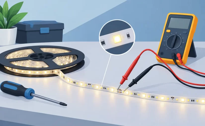
For a disconnected low-power string, a multimeter diode test can identify obvious open or shorted LEDs. Place the probes across one LED in the forward direction. A healthy red or amber LED may illuminate faintly and show a forward-voltage reading. Many white and blue LEDs require more voltage than a standard meter diode function can provide, so a non-reading does not automatically prove failure.

A dedicated LED tester is more effective for longer series strings because it can supply controlled current at a higher voltage. Begin at the lowest appropriate current. The purpose is to confirm conduction and locate the interruption, not to operate the LEDs at normal brightness. On a long string, a tester that indicates no current flow usually points to an open LED, open trace, disconnected wire, or reverse-polarity test connection.

When testing surface-mount LEDs on a populated board, probe placement matters. Oxidized pads, solder mask, and closely spaced components can create false readings. Fine insulated probes or tweezer-style probes provide more repeatable contact than standard large test leads. A component measurement instrument such as Siborg’s Smart Tweezers can also help verify nearby resistors, capacitors, and damaged interconnect components without removing every part from the board.

Find opens, shorts, and bypassed LEDs

An open LED is the most common reason a series string goes dark. In diode mode, it may show overload in both directions. In a powered string, voltage often appears across the failed device or across the section containing it, while no current flows through the complete path. Test from section to section rather than probing every device immediately. Halving the suspected path repeatedly is faster on long strips and panels.

A shorted LED can be less obvious because the remaining LEDs may still illuminate. The symptom may be a dark spot in a backlight, uneven brightness, excess current in a constant-voltage branch, or a driver that cannot regulate correctly. A shorted device often reads very low resistance or near-zero voltage in both probe directions, though parallel circuit paths can mask the result.

Some products intentionally include shunt devices across LEDs. These bypass a failed open LED so the rest of the string remains lit. A dim or dark individual LED in an otherwise operating string may therefore indicate a valid shunt action, not a wiring fault. Replace the LED and inspect the shunt circuit if uniform illumination is required.

Check current, not just light output

An LED can illuminate and still be part of a failing assembly. Measure branch current and compare parallel branches under the same operating condition. A branch drawing significantly more current may contain a shorted LED, incorrect resistor value, or regulator fault. A low-current branch may have increased resistance in a connector, cracked solder joint, degraded resistor, or partially failed LED.

Use voltage measurements across current-setting resistors to calculate current from Ohm’s law. This is often safer and more informative than opening a high-current path to insert an ammeter. On constant-current drivers, verify that measured current is within the LED board’s specified range. Excess current raises junction temperature, shifts color, accelerates lumen loss, and can cause repeated field failures.

Thermal behavior should also be evaluated after the electrical fault is repaired. An infrared camera is useful, but even a careful temperature comparison can reveal a hot resistor, regulator, or LED package. A replacement LED with the wrong forward voltage, package thermal resistance, bin, or current rating can create a new imbalance in the string.

Confirm the repair under realistic operation

After replacing a component or repairing a trace, test the assembly first at controlled current or reduced input power where possible. Then operate it at normal voltage, normal dimming level, and normal enclosure condition. Observe startup, steady-state current, brightness uniformity, and driver temperature long enough for thermal regulation to stabilize.

Document the failed component location, forward-voltage behavior, branch current, and driver output. That record matters in production and field service because repeated failures often reveal a design, assembly, or environmental issue rather than isolated defective LEDs.

The most efficient LED-string repair is not the one that restores light fastest. It is the one that identifies whether the LED, interconnect, current-control circuit, or operating conditions caused the failure – and verifies that the repaired string will remain within its electrical and thermal limits.

7 Best Handheld Impedance Analyzers for PCB Work

A failed 0402 capacitor does not wait for a bench instrument, a clip lead setup, or a second pair of hands. The best handheld impedance analyzers reduce the distance between a suspected component and a defensible measurement, especially when troubleshooting populated PCBs, sorting SMD parts, or verifying incoming components.

For many repair and production tasks, the right handheld instrument is not simply the smallest LCR meter available. It must provide useful test frequencies, stable contact at the component, sufficient basic accuracy, and readings that can be interpreted in the circuit context. The best choice depends on whether the work centers on loose parts, board-level diagnostics, high-frequency capacitors, inductors, ESR, or documented quality-control measurements.

What Makes a Handheld Impedance Analyzer Useful?

Impedance is more than resistance. A real component may exhibit capacitance, inductance, equivalent series resistance (ESR), dissipation factor, quality factor, phase angle, or a combination of these characteristics at a given test frequency. A handheld impedance analyzer or advanced LCR meter applies a known AC stimulus and reports the resulting electrical behavior.

That distinction matters on modern boards. A ceramic capacitor that appears acceptable at a low test frequency can behave differently at 100 kHz or 250 kHz. An inductor’s DC resistance does not establish its AC impedance. A capacitor with elevated ESR may cause power-rail instability even when its nominal capacitance still appears close to specification.

Portable instruments also impose practical constraints. Test leads are flexible but can add parasitic inductance and capacitance, pick up noise, and make repeatable contact difficult on fine-pitch assemblies. For SMD work, direct tweezer-style probes often provide a faster and more controlled measurement path.

The 7 Best Handheld Impedance Analyzer Fits

There is no single best handheld analyzer for every electronics task. The following categories identify the capability set that produces the best result for a specific workflow.

1. Best for Direct SMD Measurement: Tweezer-Style LCR Instruments

For technicians locating questionable resistors, capacitors, and inductors on a populated PCB, a tweezer-style instrument is usually the most efficient format. The probes contact both terminations directly, allowing the user to measure a component without balancing loose leads or positioning clips in a crowded area.

This approach is particularly valuable for 0201, 0402, 0603, and similar SMD packages. It also reduces the time required to sort loose parts from reels, trays, or repair bins. Smart Tweezers and LCR-Reader instruments from Siborg Systems are designed around this direct-contact measurement method, with configurations ranging from compact budget instruments to advanced Bluetooth-enabled tools.

In-circuit results still require judgment. Parallel components, semiconductor junctions, and connected power rails can influence the reading. Direct probing speeds up diagnosis, but it does not eliminate the need to isolate a component when the circuit topology makes a measurement ambiguous.

2. Best for High-Frequency Capacitor Work: 100 kHz or 250 kHz Testing

Test frequency should be a purchase criterion, not a secondary specification. Low-frequency measurements can be suitable for many general-purpose components, but higher-frequency testing is more revealing for MLCCs, small inductors, switching power supplies, RF-adjacent circuits, and low-impedance capacitors.

A 100 kHz test capability is a practical minimum for many professional capacitor and ESR applications. A 250 kHz option extends useful analysis for users who need closer alignment with high-frequency operating conditions. It is not automatically better for every component, since component datasheets specify measurement conditions for a reason. The goal is to select an instrument that can test near the frequencies relevant to the failure mechanism or acceptance requirement.

3. Best for Production Verification: High Basic Accuracy

For incoming inspection, repair documentation, and controlled production work, basic accuracy matters more than a long feature list. An instrument with 0.1% or 0.2% basic accuracy provides a stronger basis for distinguishing actual component variation from measurement uncertainty.

Accuracy specifications should be read with their conditions attached. Check the specified frequency, measurement range, test signal level, and calibration interval. A headline accuracy number does not guarantee identical performance at every impedance level or at the upper end of the frequency range.

Repeatability is equally important on the bench. If operators cannot contact the same small component consistently, an accurate measurement engine will not solve the workflow problem. Probe geometry, contact pressure, and clean test surfaces all affect usable results.

4. Best for ESR Troubleshooting: Instruments With ESR and LCR Modes

Capacitor failures often appear as increased ESR rather than an obvious loss of capacitance. A handheld analyzer that reports capacitance, ESR, and related LCR parameters gives repair specialists a more complete diagnostic view, particularly on switching regulator outputs and aging electrolytic capacitors.

ESR should not be treated as a pass-fail value without context. ESR changes with capacitance, voltage rating, construction, temperature, and frequency. Compare the result with the component type, circuit role, and manufacturer data when available. A very low ESR reading can also be affected by parallel capacitors on a board.

5. Best for PCB Fault Isolation: Oscilloscope and Analog Signature Capabilities

An impedance measurement is most useful when it can be combined with another diagnostic perspective. Instruments that integrate oscilloscope functions or Analog Signature Analysis can help identify differences between equivalent circuit nodes, compare a known-good board with a suspect board, and assess semiconductor-related behavior.

This capability is not necessary for simple component sorting. It becomes valuable when the fault is not isolated to one visibly damaged part and the technician needs to compare circuit behavior without immediately powering the board. For repair organizations handling mixed boards and intermittent faults, combining measurement functions can reduce tool changes and bench space.

6. Best for Traceable Quality Work: Calibration-Supported Instruments

A measurement is more useful in a quality system when its calibration status is documented. Laboratories, contract manufacturers, and organizations with audit requirements should consider handheld instruments supplied with NIST Traceable Calibration Certificates or supported by a defined calibration process.

Calibration documentation does not replace proper measurement technique. Users still need to follow zeroing procedures, protect probe contacts, avoid measuring energized circuits, and verify readings with appropriate standards when the application demands it. It does provide a documented starting point for confidence in the instrument’s performance.

7. Best for Digital Records: Bluetooth-Enabled Measurement Tools

Manual transcription is slow and introduces avoidable errors. Bluetooth-enabled handheld instruments can transfer measurements to mobile devices or PCs for recording, comparison, and reporting. This is especially useful when technicians must capture a series of component values, document repair evidence, or share results with engineering teams.

Wireless connectivity should support the work rather than complicate it. Confirm that the application or PC workflow provides the required data format, operating system compatibility, and measurement capture speed. For a technician making a few measurements per day, a standalone display may be sufficient. For repeated inspection or repair documentation, digital capture can save meaningful time.

How to Compare Handheld Impedance Analyzers Before Buying

Start with the components and circuits you measure most often. A repair technician working primarily on compact consumer PCBs will likely value fine-pitch tweezer probes, auto-identification, fast readings, and high-frequency capacitor testing. A quality technician may prioritize basic accuracy, calibration traceability, and repeatable measurement procedures. An engineer diagnosing power electronics may need ESR data, inductance measurements, and waveform or signature-analysis capability.

Then examine the specifications that affect the actual measurement: test frequencies, impedance ranges, basic accuracy, available LCR and ESR parameters, test signal conditions, display readability, battery operation, probe replacement options, and data connectivity. Do not assume that a conventional handheld multimeter can replace an impedance analyzer. A DMM is indispensable for voltage, continuity, and resistance checks, but it does not provide the same AC component characterization.

Also consider the physical point of contact. Test leads remain useful for larger through-hole components and remote nodes. Dedicated tweezer probes are typically faster for small components and dense PCB work. The best setup may include both, rather than forcing one probe style into every measurement.

A handheld impedance analyzer earns its place at the bench when it shortens the path from symptom to evidence. Select the frequency range, accuracy, probing method, and documentation features that match the boards in front of you, then use each reading as part of the circuit diagnosis rather than as an isolated number.

How to Test Relays With a Digital Multimeter

A relay can click positively and still fail under load. Pitted contacts, a weak coil, oxidized terminals, or an intermittent PCB solder joint can leave a control circuit unreliable while a quick continuity check appears normal. Knowing how to test relays means verifying the coil, the contact states, and the relay’s behavior at its rated operating voltage.

For repair, production, and field diagnostics, test the relay out of circuit whenever practical. A populated board can create parallel paths through drivers, suppression diodes, lamps, motors, and other loads that make otherwise valid measurements misleading. When removal is not practical, use the schematic and relay pinout to isolate what the meter is actually measuring.

Identify the Relay Terminals Before Measuring

Do not rely on terminal position alone. Automotive, PCB, power, reed, latching, and signal relays can use very different pin arrangements. Read the marking on the relay case, then confirm the manufacturer’s datasheet or the board silkscreen. Identify the two coil terminals and the switching terminals: common, normally open, and normally closed.

A single-pole double-throw relay has a common terminal that connects to the normally closed contact when the coil is de-energized. When the coil is energized, common transfers to the normally open contact. A single-pole single-throw relay has only one switched path, usually normally open. Latching relays require special attention because their contact state remains after the coil pulse is removed.

Disconnect power before resistance or continuity measurements. Also discharge capacitors in the circuit. A relay may be low voltage, but the equipment around it may store hazardous energy or contain mains-referenced circuitry.

Tools for Testing a Relay

A digital multimeter with resistance, continuity, and DC voltage functions covers most relay checks. A regulated bench supply set to the relay’s rated coil voltage is the preferred way to verify operation off the board. Set an appropriate current limit before energizing an unknown relay.

For contact resistance and borderline faults, a meter capable of low-resistance measurement is more useful than a basic audible continuity function. Continuity only confirms that resistance is below a threshold set by the meter. It does not establish that a power relay contact can carry rated current with acceptably low voltage drop.

For compact PCB relays, fine probes or tweezer-style probes improve terminal access and reduce the chance of bridging adjacent pads. An LCR meter can also measure coil inductance, but inductance alone does not prove correct actuation or contact performance. Siborg handheld component instruments are particularly useful where relay terminals and surrounding SMD components must be probed directly on a dense board.

How to Test Relays: Coil Resistance and Isolation

With the relay de-energized and preferably removed from the circuit, measure resistance across the coil terminals. Compare the reading with the relay datasheet, if available. Coil resistance varies substantially by relay voltage, package, and coil power rating, so there is no universal acceptable value.

An open reading, often shown as OL or overload, usually indicates a broken coil winding, damaged lead, or failed internal connection. A reading near zero ohms can indicate a shorted winding, although low-voltage, high-current relay coils can legitimately measure only a few ohms. The useful question is whether the measured value is plausible for that specific relay and consistent with the specification.

If the relay is still installed, lift one coil lead when an accurate result matters. Semiconductor drivers, flyback diodes, and other parts connected across the coil can affect the reading. A diode across a DC coil also means polarity matters when applying an external supply. Reverse polarity may forward-bias the diode and create a near-short across the supply.

Check isolation between either coil terminal and the contact terminals. A conventional electromechanical relay should show very high resistance between these sections with no power applied. Any measurable low-resistance path suggests contamination, internal damage, or an incorrect terminal identification. Do not use a high-voltage insulation tester on a relay connected to sensitive electronics unless the circuit and component ratings specifically allow it.

Verify Normally Open and Normally Closed Contacts

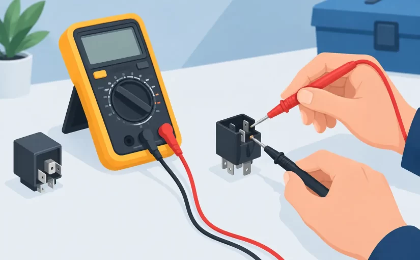
Set the multimeter to resistance or continuity. With the coil unpowered, measure from common to normally closed. This path should be closed, usually with a resistance near the meter lead resistance for a clean small-signal relay. Common to normally open should be open.

Now energize the coil with its specified DC or AC voltage, as applicable. For a DC relay, begin at the rated coil voltage rather than guessing. The contact states should reverse: common to normally open should close, and common to normally closed should open.

A click is useful confirmation of mechanical movement, but it is not a complete test. Record the resistance of the closed contact path before and after actuation. First short the meter probes together and note their resistance. If a relay measures substantially above that baseline, inspect for burned or oxidized contacts. The acceptable value depends on relay type. Signal relays may be specified in milliohms, while a worn power relay may still pass a basic continuity test yet cause enough voltage drop to prevent a motor, heater, or solenoid from operating correctly.

Test Pickup, Dropout, and Actual Coil Drive

A relay can pass a bench test and still fail in equipment because the driver circuit cannot deliver enough coil voltage or current. Measure voltage directly across the coil terminals while the circuit commands the relay on. Compare this value with the relay’s rated coil voltage and pickup specification.

Low coil voltage can result from a weak transistor or MOSFET driver, a poor ground, corroded connector, damaged trace, current-limited control module, or excessive supply sag. If the coil is powered through a transistor, measure the voltage across the driver as well. A high voltage drop across a saturated switching transistor points to a driver or control problem rather than the relay.

On a bench supply, slowly increase coil voltage while observing the contact transition. The pickup voltage is the point at which the relay changes state. Reduce the voltage to find dropout. Compare both values to the datasheet, recognizing that temperature and relay orientation can affect the result. Do not hold a relay coil above its rated voltage in an attempt to force operation. Overdrive can overheat the winding and create a new failure.

For intermittent faults, gently flex the relay pins and board area while monitoring coil voltage and contact continuity. Cracked solder joints at relay terminals are common in equipment exposed to vibration, heat cycling, or high contact current. Inspect both sides of the PCB for ring cracks, darkened pads, and overheated traces.

Confirm Contact Performance Under Load

No-load resistance testing cannot reveal every contact defect. A relay that switches a few milliamps from a meter may fail when it must carry a motor inrush current, lamp load, or inductive solenoid current. When safe and appropriate, test the relay in a controlled circuit with a representative load.

Measure voltage drop across the closed contacts while current is flowing. A healthy closed contact should have a low drop relative to the circuit voltage. Excessive drop indicates contact resistance, which creates heat according to I²R. A relay carrying several amps can develop damaging heat from resistance that seemed insignificant during an ohmmeter check.

Use caution with mains-powered, high-current, and inductive loads. A fused test setup, suitable isolation practices, and correctly rated probes are required. If contact welding is suspected, disconnect power and verify whether normally open contacts remain closed when the coil is de-energized. Welded contacts are a replacement condition, not a cleaning opportunity in most sealed PCB relays.

Common Results and What They Mean

An open coil indicates a failed relay. Correct coil resistance with no movement at rated voltage suggests mechanical binding or insufficient applied current. A relay that clicks but has high closed-contact resistance usually has worn, contaminated, or burned contacts. Correct operation on the bench but not in the product usually directs attention to coil drive voltage, solder joints, connectors, or the load circuit.

Replacement should match more than coil voltage. Verify contact arrangement, contact current and voltage ratings, coil type, pin layout, switching speed where relevant, and required approvals. A substitute with a different coil current can overload a transistor driver, while a different footprint can create unreliable PCB mounting.

A disciplined relay test separates the coil, the contacts, and the control circuit into measurable sections. That approach finds the actual failed element quickly and prevents a good relay from being replaced when the fault is a weak driver, damaged trace, or load-side problem.

PCB Miniaturization Testing: What Changes

A 0201 capacitor, a 0.4 mm-pitch BGA escape route, and a densely populated RF section create the same problem from different directions: there is less physical access, less measurement margin, and more opportunity for the test method to alter the result. PCB miniaturization testing is therefore not simply conventional inspection performed with smaller probes. It is a measurement discipline built around contact geometry, parasitic effects, fixture design, test frequency, and a clear understanding of what the circuit contributes around the component under test.

PCB Miniaturization Testing Starts With Access

As component packages shrink, landing pads and exposed test points become scarce. A conventional pair of hand probes can bridge adjacent pads, scrape solder mask, or apply enough force to disturb a marginal joint. Even when contact is achieved, probe placement may add variable lead length and contact resistance that masks the value being measured.

Fine-point tweezer probes address part of this problem because they allow an operator to contact both ends of a chip resistor, capacitor, or inductor directly. The benefit is not just speed. Holding the component between closely spaced probe tips reduces the measurement loop compared with long test leads, improving repeatability on low-impedance and high-frequency measurements.

Tip selection matters. Tips that are too wide can contact solder fillets, neighboring pads, or parallel circuit paths. Tips that are excessively sharp may damage small passive components or penetrate protective coatings. For repeated production or repair work, the target is controlled contact force and repeatable placement, not maximum pressure. Operators should approach the component from a stable angle, confirm that each tip is centered on the intended termination, and release pressure as soon as a stable reading is captured.

Why Smaller Boards Produce Different Errors

Miniaturized assemblies often combine low-value passives, fast digital edges, compact power stages, and RF-sensitive traces within a small area. At that scale, the instrument, probe, and board form one measurement system.

Lead inductance and stray capacitance become more significant as component values decrease and test frequency rises. A few millimeters of probe path may be inconsequential when checking a 100 kOhm resistor at low frequency. The same geometry can materially affect measurement of a 1 nH inductor, a low-ESR ceramic capacitor, or a sub-ohm current-sense resistor. Contact resistance also becomes a dominant error source when evaluating solder joints, fuses, and low-value resistors.

This is why open and short compensation should be performed with the actual probe arrangement whenever the instrument supports it. Compensation cannot eliminate every board-level effect, but it establishes a reference for the cable, fixture, or probe tips being used. If an adapter is changed, tips are replaced, or a long lead is introduced to reach a constrained location, repeat the compensation rather than assuming the previous correction remains valid.

A stable reading is not automatically a correct reading. On a populated board, the meter may be measuring the intended component in parallel with other components, semiconductor junctions, integrated-circuit protection structures, or power rails. The correct interpretation depends on the schematic and the circuit state.

In-Circuit Measurements Need Context

An in-circuit capacitance reading can be useful for quickly comparing one location with a known-good board, identifying an obvious shorted capacitor, or screening a suspect decoupling network. It may not represent the component’s marked value. Several capacitors in parallel, nearby semiconductor paths, and residual charge can all influence the result.

Resistance measurements have similar limitations. A resistor connected to an IC input may show a value affected by internal bias networks. A low reading across a supply rail can indicate a fault, but it can also reflect normal charging behavior as the meter applies its test signal. Before assigning a failed component, compare the result with the schematic, isolate the relevant net where practical, and observe whether the measured value changes with probe polarity or test voltage.

For capacitance, inductance, and ESR work, test frequency is also part of the result. A component’s impedance behavior at 1 kHz is not the same as its behavior at 100 kHz or 250 kHz. Higher-frequency testing can reveal characteristics closer to a component’s operating environment, particularly for switching power supplies and high-speed decoupling applications. It can also make fixture and contact quality more critical. Use the frequency that answers the engineering question, rather than selecting the highest available frequency by default.

Build a Test Sequence That Protects the Board

The most efficient troubleshooting process moves from low-risk inspection to targeted electrical measurement. Start with magnification and lighting. Look for cracked terminations, tombstoned passives, solder bridges, lifted pads, discoloration, and contamination. Small defects are often easier to identify visually than electrically, especially when multiple components share the same net.

Next, verify that the board is unpowered and discharged before using resistance, LCR, or ESR functions. Large capacitors can retain charge after power removal, while sensitive IC inputs may be affected by an uncontrolled test condition. For assemblies with batteries, supercapacitors, or multiple supply domains, confirm that every energy source is disconnected.

Then establish a baseline. A known-good board, a documented production sample, or a measured reference component gives far more diagnostic value than a single isolated reading. On dense assemblies, relative comparison is often the fastest way to find an outlier. If one ceramic capacitor on a rail measures distinctly differently from identical adjacent capacitors, further investigation is justified even if the absolute in-circuit reading is not definitive.

For work instructions and quality-control procedures, define acceptance criteria before testing begins. Useful criteria include:

  • permitted probe locations and the required magnification level
  • instrument function, test frequency, and compensation procedure
  • allowable reading range or comparison method
  • whether the board must be unpowered, partially isolated, or depopulated
  • required documentation for failures, rework, and retest

This level of control prevents a common failure in miniaturized-board testing: different operators reaching different conclusions because they used different contact points, frequencies, or instrument settings.

Select Instruments for the Measurement, Not the Package Size

A small handheld instrument is valuable at the bench, in field service, and on a production floor, but portability alone does not establish measurement capability. Evaluate basic accuracy, resolution, frequency range, test signal characteristics, input protection, and the physical probe system together.

For passive-component identification and board-level troubleshooting, a handheld LCR meter with direct tweezer-style contact can reduce setup time dramatically. It is particularly effective when checking unmarked SMD components, sorting removed parts, confirming resistor values, or comparing suspect passives on a board. An ESR function adds useful screening capability for capacitors in power circuits, although results must still be interpreted with the surrounding circuit in mind.

Advanced diagnostic functions can add another layer of evidence. Analog Signature Analysis compares the current-voltage response of a node or component under a controlled AC stimulus. It can help locate differences between a defective board and a reference board when a conventional resistance or capacitance reading is ambiguous. Oscilloscope capability is similarly useful when the problem is dynamic, such as an unstable supply rail, intermittent signal, or switching waveform that cannot be diagnosed with static measurements.

Siborg Systems instruments are designed around this direct-contact workflow, combining compact tweezer probing with LCR, ESR, and selected advanced measurement functions. The practical advantage is reduced handling time at the component level, provided the operator still applies the same discipline around compensation, test conditions, and circuit interpretation.

Calibration and Repeatability Are Production Requirements

Miniaturization raises the cost of a wrong decision. Removing a tiny component unnecessarily can damage pads or introduce a new assembly defect. Passing a marginal connection can create an intermittent field failure that is difficult to reproduce. Measurement confidence must therefore be supported by more than a displayed value.

Use instruments with appropriate calibration support and maintain records that connect the instrument to the work performed. A NIST-traceable calibration certificate is particularly relevant where results support quality documentation, customer returns analysis, or controlled manufacturing processes. Between formal calibrations, inspect probe tips for wear, contamination, oxidation, and loss of alignment. A damaged tip can produce inconsistent contact long before the instrument itself is out of tolerance.

Repeatability should be checked in the actual workflow. Measure a reference component or known-good board location multiple times, with normal operator handling, and observe the spread. If readings vary excessively, investigate probe pressure, tip geometry, board cleanliness, fixture movement, compensation, and test frequency before tightening acceptance limits.

Small assemblies do not make testing impossible. They make uncontrolled testing expensive. When probe access, parasitics, frequency, circuit loading, and calibration are treated as part of the measurement, compact PCBs can be evaluated quickly without sacrificing the evidence needed to make a sound repair or quality decision.

Variable Current Testing Guide for PCB Diagnostics

A component that looks normal at one test current can fail immediately when the stimulus changes. That is why a variable current testing guide is more useful than a single pass/fail reading when troubleshooting LEDs, diodes, transistor junctions, low-value resistors, protection devices, and suspect power rails on a PCB. Controlled current reveals where a device changes state, heats excessively, clamps unexpectedly, or departs from its expected I-V characteristic.

Variable-current work is not a substitute for standard resistance, capacitance, inductance, ESR, or continuity measurements. It adds a controlled stress condition to those measurements. The objective is to apply only as much current as necessary, observe the resulting voltage or behavior, and compare that response with the circuit design, a known-good board, or the component data sheet.

What Variable Current Testing Measures

A variable current test applies a known current to a device under test and measures the resulting voltage. Repeating the measurement at several current levels produces an I-V relationship: current on one axis and voltage on the other. For linear components, the relationship should be predictable. For semiconductor devices, the curve is intentionally nonlinear.

A resistor should show a proportional voltage increase as current rises. A diode should show a forward-voltage increase that follows its semiconductor junction behavior. An LED should begin emitting at a threshold region, then increase in brightness as forward current rises. A transient-voltage suppressor, zener diode, or clamp circuit may remain largely inactive until its specified breakdown or clamping region.

This approach is especially effective when a defect is intermittent or marginal. A cracked solder joint may appear open only when the test current is high enough to create a measurable voltage drop. A damaged LED may illuminate weakly at a low current but show excessive forward voltage or unstable output at its normal operating current. A shorted bypass capacitor may look like a low resistance, but variable current can help determine whether the apparent short is a capacitor, a semiconductor rail clamp, or a downstream IC.

Start With Current Limits, Not Maximum Output

The first decision is not what current to apply. It is the maximum current the part and surrounding circuit can tolerate. A controlled current source must be set below the lowest relevant limit: the component rating, the trace capability, the connected IC limit, and the instrument’s safe operating range.

For small signal diode junction checks, microamp or low-milliamp levels are often sufficient. For indicator LEDs, start at a few hundred microamps or 1 mA before moving toward the intended operating current. A 0402 resistor may be electrically intact but easy to overheat if excessive current is applied for too long. For an in-circuit rail, even a low current can energize unexpected paths through ESD diodes, regulators, logic inputs, and parallel loads.

Use short test intervals. Record the voltage quickly, then release the stimulus and allow the component to return to ambient temperature. If voltage drifts while current remains constant, determine whether the drift is normal thermal behavior or evidence of a poor connection, leakage path, or component breakdown.

Variable Current Testing Guide: A Controlled Procedure

Disconnect external power before injecting current into an unpowered circuit unless the test plan specifically requires powered operation. Remove batteries, disconnect adapters, and discharge high-voltage capacitors. Confirm that no supply rail remains energized through USB, communication cables, backup cells, or connected test equipment.

Begin by identifying the test node and return path. On a loose component, the path is obvious. On a populated board, it may not be. Review the schematic or trace the copper carefully enough to understand what else is connected. A current injected into a 3.3 V rail may divide among many ICs and capacitors, which makes the measurement unsuitable for identifying one component without further isolation.

Set the current source to its minimum useful output. Connect the positive lead or probe to the intended test point and the return lead to circuit ground or the component’s other terminal. Measure voltage directly across the device whenever possible. Measuring only at the source output can include lead, clip, probe, and PCB trace resistance.

Increase current in deliberate steps. The appropriate step size depends on the device. A 10 µA, 100 µA, 1 mA, and 5 mA sequence may suit a diode or leakage investigation. A resistor may be checked at two or three levels selected to produce easily measured voltages while remaining below its power rating. Record current, measured voltage, time under test, and any visible or thermal response.

Calculate resistance for linear parts using R = V/I at each point. If the calculated value changes significantly, first verify probe contact and lead resistance. Then consider temperature coefficient, self-heating, a parallel in-circuit path, or a component that is not behaving as a resistor should.

Interpreting Common Component Responses

Resistors and Current-Sense Paths

For resistors, the key question is whether voltage rises proportionally with current. A 1 ohm current-sense resistor should produce approximately 10 mV at 10 mA and 100 mV at 100 mA. Use four-wire measurement when low resistance and lead resistance are comparable. Two-wire probing can make a correct low-value resistor appear high, especially with long leads or oxidized contact points.

A result that changes with applied current can also expose a compromised solder joint. If the resistor itself is within tolerance but the voltage drop across the complete path rises unexpectedly, measure across individual joints and trace segments to locate the added resistance.

Diodes, LEDs, and Protection Devices

A forward-biased silicon diode commonly shows a lower forward voltage at low current and a higher value as current increases. The exact values depend on junction type and temperature. Do not reject a part simply because its forward voltage differs from a generic diode-test expectation. Compare like parts, data-sheet conditions, and circuit function.

With LEDs, observe both forward voltage and light output. A dim or nonuniform LED may still conduct normally at low current. Increasing current within the rated limit can reveal poor die connection, internal damage, or a color shift. Use a current-limited source rather than a fixed-voltage supply. A small voltage increase above the LED’s forward threshold can produce a large and damaging current increase.

For zeners and TVS devices, test in both directions as appropriate. Forward behavior resembles a conventional diode. Reverse testing requires special care because breakdown may occur at a voltage that exceeds handheld instrument capability, and the device can dissipate substantial power. Apply only enough current to confirm the expected knee or clamp behavior.

Capacitors and PCB Supply Rails

Variable-current injection is useful for locating hard shorts on supply rails, but it is not a component-value measurement. Start with a low current limit and watch the rail voltage. A rail that remains near zero volts while the source reaches its current limit has a low-resistance load or short. If voltage rises steadily, the apparent short may be normal circuit loading, a charging capacitor, or a semiconductor path.

Thermal inspection can help locate the fault, but do not use excessive current merely to make a part heat faster. Start low, increase only when justified, and stay below the estimated safe dissipation of the board and components. Sensitive ICs can be damaged before a thermal change is obvious.

Avoid Measurement Errors That Look Like Faults

The most common error is treating an in-circuit reading as an isolated component reading. Parallel resistors lower the apparent resistance. Semiconductor junctions create alternate paths. Decoupling capacitors can make a rail appear short during charging, then normal seconds later. When the result conflicts with the design expectation, isolate one terminal or compare against a verified board before replacing parts.

Probe pressure matters on small components. A handheld LCR meter or SMD test tweezers can quickly identify the component and establish a baseline value, while a separate current-limited source evaluates behavior under controlled load. Siborg Smart Tweezers instruments are particularly useful for direct access to small SMD terminals where conventional clips can slip, bridge adjacent pads, or add unstable contact resistance.

Also account for instrument burden voltage and source compliance voltage. A current source cannot maintain its programmed current if the required voltage exceeds its compliance limit. If the displayed current falls below the set value, the measured response is no longer a valid point on the intended test curve.

Document the Curve, Not Just the Final Reading

A single value rarely captures variable-current behavior. Record a short table of current and voltage points, including polarity, board condition, ambient temperature, and test duration. For recurring service work, save the readings from a known-good assembly. This turns troubleshooting from a subjective comparison into a repeatable acceptance method.

The best variable-current test is the smallest controlled stimulus that clearly separates normal behavior from a fault. Start low, measure directly at the device, and increase only when the circuit response gives you a reason to do so. That discipline protects the board while producing evidence you can trust.