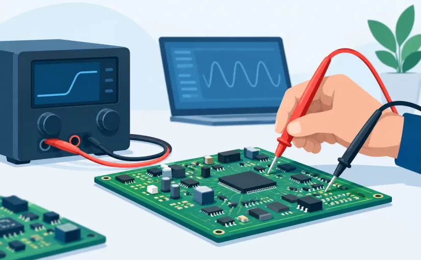
A component that looks normal at one test current can fail immediately when the stimulus changes. That is why a variable current testing guide is more useful than a single pass/fail reading when troubleshooting LEDs, diodes, transistor junctions, low-value resistors, protection devices, and suspect power rails on a PCB. Controlled current reveals where a device changes state, heats excessively, clamps unexpectedly, or departs from its expected I-V characteristic.
Variable-current work is not a substitute for standard resistance, capacitance, inductance, ESR, or continuity measurements. It adds a controlled stress condition to those measurements. The objective is to apply only as much current as necessary, observe the resulting voltage or behavior, and compare that response with the circuit design, a known-good board, or the component data sheet.
What Variable Current Testing Measures
A variable current test applies a known current to a device under test and measures the resulting voltage. Repeating the measurement at several current levels produces an I-V relationship: current on one axis and voltage on the other. For linear components, the relationship should be predictable. For semiconductor devices, the curve is intentionally nonlinear.
A resistor should show a proportional voltage increase as current rises. A diode should show a forward-voltage increase that follows its semiconductor junction behavior. An LED should begin emitting at a threshold region, then increase in brightness as forward current rises. A transient-voltage suppressor, zener diode, or clamp circuit may remain largely inactive until its specified breakdown or clamping region.
This approach is especially effective when a defect is intermittent or marginal. A cracked solder joint may appear open only when the test current is high enough to create a measurable voltage drop. A damaged LED may illuminate weakly at a low current but show excessive forward voltage or unstable output at its normal operating current. A shorted bypass capacitor may look like a low resistance, but variable current can help determine whether the apparent short is a capacitor, a semiconductor rail clamp, or a downstream IC.
Start With Current Limits, Not Maximum Output
The first decision is not what current to apply. It is the maximum current the part and surrounding circuit can tolerate. A controlled current source must be set below the lowest relevant limit: the component rating, the trace capability, the connected IC limit, and the instrument’s safe operating range.
For small signal diode junction checks, microamp or low-milliamp levels are often sufficient. For indicator LEDs, start at a few hundred microamps or 1 mA before moving toward the intended operating current. A 0402 resistor may be electrically intact but easy to overheat if excessive current is applied for too long. For an in-circuit rail, even a low current can energize unexpected paths through ESD diodes, regulators, logic inputs, and parallel loads.
Use short test intervals. Record the voltage quickly, then release the stimulus and allow the component to return to ambient temperature. If voltage drifts while current remains constant, determine whether the drift is normal thermal behavior or evidence of a poor connection, leakage path, or component breakdown.
Variable Current Testing Guide: A Controlled Procedure
Disconnect external power before injecting current into an unpowered circuit unless the test plan specifically requires powered operation. Remove batteries, disconnect adapters, and discharge high-voltage capacitors. Confirm that no supply rail remains energized through USB, communication cables, backup cells, or connected test equipment.
Begin by identifying the test node and return path. On a loose component, the path is obvious. On a populated board, it may not be. Review the schematic or trace the copper carefully enough to understand what else is connected. A current injected into a 3.3 V rail may divide among many ICs and capacitors, which makes the measurement unsuitable for identifying one component without further isolation.
Set the current source to its minimum useful output. Connect the positive lead or probe to the intended test point and the return lead to circuit ground or the component’s other terminal. Measure voltage directly across the device whenever possible. Measuring only at the source output can include lead, clip, probe, and PCB trace resistance.
Increase current in deliberate steps. The appropriate step size depends on the device. A 10 µA, 100 µA, 1 mA, and 5 mA sequence may suit a diode or leakage investigation. A resistor may be checked at two or three levels selected to produce easily measured voltages while remaining below its power rating. Record current, measured voltage, time under test, and any visible or thermal response.
Calculate resistance for linear parts using R = V/I at each point. If the calculated value changes significantly, first verify probe contact and lead resistance. Then consider temperature coefficient, self-heating, a parallel in-circuit path, or a component that is not behaving as a resistor should.
Interpreting Common Component Responses
Resistors and Current-Sense Paths
For resistors, the key question is whether voltage rises proportionally with current. A 1 ohm current-sense resistor should produce approximately 10 mV at 10 mA and 100 mV at 100 mA. Use four-wire measurement when low resistance and lead resistance are comparable. Two-wire probing can make a correct low-value resistor appear high, especially with long leads or oxidized contact points.
A result that changes with applied current can also expose a compromised solder joint. If the resistor itself is within tolerance but the voltage drop across the complete path rises unexpectedly, measure across individual joints and trace segments to locate the added resistance.
Diodes, LEDs, and Protection Devices
A forward-biased silicon diode commonly shows a lower forward voltage at low current and a higher value as current increases. The exact values depend on junction type and temperature. Do not reject a part simply because its forward voltage differs from a generic diode-test expectation. Compare like parts, data-sheet conditions, and circuit function.
With LEDs, observe both forward voltage and light output. A dim or nonuniform LED may still conduct normally at low current. Increasing current within the rated limit can reveal poor die connection, internal damage, or a color shift. Use a current-limited source rather than a fixed-voltage supply. A small voltage increase above the LED’s forward threshold can produce a large and damaging current increase.
For zeners and TVS devices, test in both directions as appropriate. Forward behavior resembles a conventional diode. Reverse testing requires special care because breakdown may occur at a voltage that exceeds handheld instrument capability, and the device can dissipate substantial power. Apply only enough current to confirm the expected knee or clamp behavior.
Capacitors and PCB Supply Rails
Variable-current injection is useful for locating hard shorts on supply rails, but it is not a component-value measurement. Start with a low current limit and watch the rail voltage. A rail that remains near zero volts while the source reaches its current limit has a low-resistance load or short. If voltage rises steadily, the apparent short may be normal circuit loading, a charging capacitor, or a semiconductor path.
Thermal inspection can help locate the fault, but do not use excessive current merely to make a part heat faster. Start low, increase only when justified, and stay below the estimated safe dissipation of the board and components. Sensitive ICs can be damaged before a thermal change is obvious.
Avoid Measurement Errors That Look Like Faults
The most common error is treating an in-circuit reading as an isolated component reading. Parallel resistors lower the apparent resistance. Semiconductor junctions create alternate paths. Decoupling capacitors can make a rail appear short during charging, then normal seconds later. When the result conflicts with the design expectation, isolate one terminal or compare against a verified board before replacing parts.
Probe pressure matters on small components. A handheld LCR meter or SMD test tweezers can quickly identify the component and establish a baseline value, while a separate current-limited source evaluates behavior under controlled load. Siborg Smart Tweezers instruments are particularly useful for direct access to small SMD terminals where conventional clips can slip, bridge adjacent pads, or add unstable contact resistance.
Also account for instrument burden voltage and source compliance voltage. A current source cannot maintain its programmed current if the required voltage exceeds its compliance limit. If the displayed current falls below the set value, the measured response is no longer a valid point on the intended test curve.
Document the Curve, Not Just the Final Reading
A single value rarely captures variable-current behavior. Record a short table of current and voltage points, including polarity, board condition, ambient temperature, and test duration. For recurring service work, save the readings from a known-good assembly. This turns troubleshooting from a subjective comparison into a repeatable acceptance method.
The best variable-current test is the smallest controlled stimulus that clearly separates normal behavior from a fault. Start low, measure directly at the device, and increase only when the circuit response gives you a reason to do so. That discipline protects the board while producing evidence you can trust.