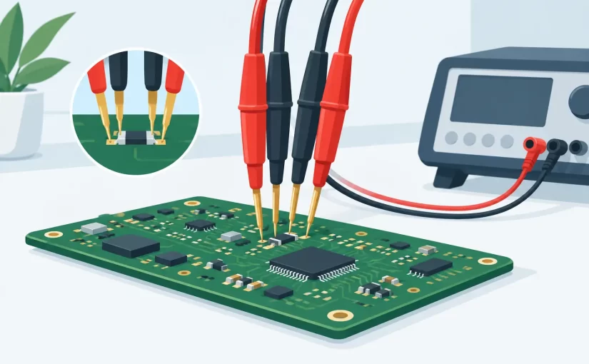
A 0.05 ohm contact error is insignificant on a 10 kilohm resistor. On a 0.10 ohm current-sense resistor, it can invalidate the measurement. That is the practical reason to learn how to use Kelvin probes: they separate the current path from the voltage-sensing path, removing much of the error caused by test leads, clips, and probe contact resistance.
Kelvin probing is not a substitute for sound measurement practice. It is a four-terminal technique that improves results when the device under test has low resistance, low impedance, or when lead and contact resistance are a meaningful part of the reading. Used correctly, it is valuable for current shunts, battery tabs, cable joints, relay contacts, PCB traces, low-value resistors, and capacitor ESR measurements.
How to Use Kelvin Probes: The Four-Wire Principle
A conventional two-wire measurement sends test current through a pair of leads and measures voltage through those same leads. The instrument therefore sees the resistance of the component plus the resistance of the leads, connections, oxidation, and probe pressure.
Kelvin probes use two separate pairs of conductors. The force pair applies a known test current to the component. The sense pair measures the voltage directly at the component terminals. Because the sensing input draws very little current, voltage drop in the sense leads is negligible. The instrument calculates resistance from the voltage measured at the device under test and the known test current.
For a two-terminal resistor, the connection order is straightforward: force current enters one terminal and returns from the other, while the sense contacts touch those same two terminals as close to the resistor body or solder joints as possible. Many Kelvin clips and Kelvin test tweezers place force and sense contacts in one compact jaw, making this arrangement faster and more repeatable.
The method does not make every reading automatically accurate. If the sense contacts are placed on a PCB trace several centimeters away from the component, the measured trace resistance is still included. That may be desirable when checking an interconnect, but it is not the same as measuring the component alone.
Select the Right Instrument Mode First
Start by choosing the measurement function that matches the fault or component. A DC low-resistance mode is appropriate for shunts, wiring, contacts, and trace continuity where resistance is the primary concern. An LCR meter is more suitable for inductors, capacitors, and resistors measured at a specified AC test frequency. ESR testing uses an AC method intended to characterize a capacitor’s effective series resistance.
Test frequency matters. A capacitor can show a low ESR at one frequency and a different value at another, particularly with electrolytic, polymer, and ceramic technologies. Inductors and ferrite components can also be frequency-dependent. Use the frequency required by the component specification or the troubleshooting condition, rather than treating a single reading as universal.
Before connecting, check four practical conditions:
- The circuit is powered down and discharged.
- The instrument range and test function suit the expected value.
- The probes, tips, and fixture are clean and mechanically sound.
- The component can be measured in circuit without a parallel path distorting the result.
A powered circuit can damage an LCR or ESR instrument and produce misleading results. Stored charge in large capacitors is equally problematic. Discharge capacitors through an appropriate resistor and verify the remaining voltage with a suitable meter before applying Kelvin probes.
Compensate the Probes and Fixture
Four-wire measurement reduces lead resistance effects, but compensation is still required for the best results, especially with LCR and ESR measurements. The exact procedure depends on the instrument, but it generally includes open and short compensation.
Open compensation measures residual capacitance and leakage associated with the fixture and probe geometry when the tips are separated. Short compensation measures residual resistance and inductance when the force and sense contacts are connected together at the probe tips. The instrument stores these values and subtracts or corrects for fixture effects during measurement.
Perform compensation using the same probes, tips, and cable arrangement that will be used for the measurement. If you change from Kelvin clips to test tweezers, replace probe tips, or alter a long cable layout, repeat the procedure. At higher test frequencies, even small changes in contact geometry and lead routing can affect parasitic inductance and capacitance.
For low-resistance work, a short check also reveals a damaged lead or contaminated contact. A compensated fixture should produce a stable near-zero reading when its Kelvin contacts are properly shorted. If the value wanders, inspect the probe jaws, cable strain relief, connector seating, and oxidation on the contact surfaces.
Make Contact at the Correct Measurement Plane
The measurement plane is the exact point where the instrument senses voltage. It determines what is included in the result.
When measuring a low-value SMD resistor, place the Kelvin contacts directly on the two solder fillets or on exposed terminal metallization. Avoid contacting distant vias or adjacent copper unless the trace resistance is part of the test objective. For a cable assembly, place the sense contacts at the two points whose resistance must be verified, not at convenient locations farther up the harness.
Contact pressure should be firm enough to break through light surface films but not so high that it damages pads, small components, or conformal coating. On fine-pitch boards, sharp and well-aligned tips are more useful than excessive force. A stable fixture or tweezer-style probe reduces hand movement and helps maintain repeatable contact on 0201, 0402, and similar small packages.
Kelvin probes are especially effective when the force contacts are outside the sense contacts, or when a purpose-built clip maintains the correct geometry. Do not improvise by placing two ordinary probe tips on each terminal unless spacing and stability allow the force and sense points to remain distinct. On small components, dedicated Kelvin tweezers or closely spaced four-wire probe accessories are usually the practical solution.
Measure In Circuit With Caution
In-circuit Kelvin testing is fast, but the board can create parallel paths that are invisible at first glance. A 1 ohm resistor may be connected to other resistors, semiconductor junctions, IC inputs, or copper planes that alter the reading. A capacitor ESR measurement may be influenced by parallel capacitors, regulators, or protection devices.
Use the schematic and board layout to decide whether the reading is meaningful. If the measured value is lower than expected, look for parallel components or alternate current paths. If it is higher, inspect solder joints, cracked terminations, corroded vias, fuses, connectors, and damaged copper. A comparison with an identical channel or known-good board is often more useful than comparing only against a nominal component value.
For critical component verification, isolate one terminal or remove the component. This takes more time but eliminates ambiguity. The appropriate choice depends on the cost of a false diagnosis, the accessibility of the component, and whether the board is a repair unit, production sample, or qualification article.
Reading Low Resistance, ESR, and Inductance Results
A good Kelvin reading is stable, repeatable, and technically plausible. Take several readings while lightly repositioning the probe. If the value changes significantly, suspect contact quality before declaring the component defective. Oxidation, flux residue, worn probe tips, and insufficient jaw alignment commonly cause unstable low-ohm readings.
For resistors, compare the result with the nominal value and tolerance, while accounting for temperature coefficient and in-circuit paths. For current shunts, measure at the intended pad locations because milliohms of copper can matter. For relay contacts or connectors, measure under the specified mechanical state and, where appropriate, under a test current representative of service conditions.
For capacitors, do not interpret ESR without considering capacitance, voltage rating, technology, temperature, and test frequency. A low ESR value is not automatically good if capacitance has fallen substantially. Likewise, ceramic capacitors may have very low ESR while still exhibiting a crack or DC-bias-related performance issue that requires another test method.
Advanced handheld LCR instruments can combine Kelvin-compatible probing with higher test frequencies and component identification functions. In PCB repair, compact tweezer-style measurement can reduce the time required to move from suspected component to verified result, provided the operator still controls the measurement plane and understands the surrounding circuit.
Common Kelvin Probe Errors
The most frequent error is assuming four wires eliminate every source of uncertainty. Kelvin measurement removes most voltage error caused by the force leads, but it cannot correct for poor sense contact, a contaminated pad, thermal effects, electromagnetic interference, or an unsuitable test frequency.
Another common problem is crossing or misidentifying force and sense connections on separate clips. Follow the instrument labeling and keep each terminal’s force and sense contacts paired at the same end of the device under test. On long leads, route force and sense conductors together and avoid large loops that can pick up noise, especially during AC impedance measurements.
Finally, protect the probes. Kelvin tips are precision contacts, not general-purpose scraping tools. Clean them with an electronics-safe method, replace worn points, and verify compensation before measurement sessions where milliohm-level repeatability matters.
A Kelvin probe earns its place on the bench when the difference between a component fault and a connection fault is only a few milliohms. Put the sense contacts at the true test point, compensate the fixture, and let the measurement answer the question you actually need to ask.