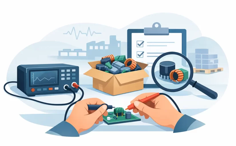
A component reel can carry the correct manufacturer label, date code, and stated value yet still be unsuitable for production. Counterfeit parts, storage damage, incorrect substitutions, moisture exposure, and lot-to-lot variation all reach receiving docks. An LCR meter for incoming inspection gives quality teams a fast, quantitative way to confirm that passive components match the purchase specification before they are released to the line.
This is not a replacement for supplier qualification, visual inspection, or full reliability testing. It is a practical control point that catches electrical discrepancies early, when a rejected lot is still traceable and a production stop has not become a field failure. The most effective programs define what to measure, at which test conditions, and how much variation is acceptable before the first sample is tested.
Start with the component specification, not the nominal value
Incoming inspection often fails when a technician checks only the printed value. A 10 uF capacitor, for example, is not fully described by capacitance. Its acceptable result depends on tolerance, voltage bias behavior, dielectric type, dissipation factor or ESR limit, test frequency, and sometimes DC bias. A 10 uH inductor likewise requires a specified test frequency and signal level because inductance can shift with core material, winding construction, and applied current.
The purchase specification should state the measurement conditions used by the component manufacturer. These commonly include test frequency, AC test voltage or current, equivalent circuit model, and temperature. If the supplier data sheet specifies 1 kHz at 1 V RMS, a receiving measurement at 100 kHz with a different equivalent model is useful for screening but cannot be directly compared with the catalog tolerance.
For resistors, incoming checks are usually straightforward: measure resistance at a stable low test level and compare it with the stated tolerance. For capacitors and inductors, the test condition is part of the requirement. Record it on the inspection plan rather than leaving it to operator judgment.
Choose an LCR meter for incoming inspection by test conditions
Basic accuracy matters, but it is only one part of a capable receiving instrument. The meter must measure the component at frequencies relevant to its specification and application. A general-purpose unit operating at 100 Hz, 120 Hz, 1 kHz, and 10 kHz may be appropriate for many bulk capacitors, inductors, and resistors. High-frequency ceramic capacitors, RF inductors, and small SMD parts often require 100 kHz or higher to expose differences that do not appear at 1 kHz.
A meter with test frequencies up to 250 kHz expands screening capability for high-frequency components and small-value inductors. It does not mean every incoming part should be tested at 250 kHz. The correct frequency remains the one defined by the data sheet, customer requirement, or validated internal method.
Also evaluate basic accuracy at the expected measurement range, not the headline figure alone. A 0.1% or 0.2% basic accuracy specification can support tight incoming limits, but fixture effects, contact resistance, operator technique, and component tolerance contribute to the total uncertainty. For a 5% component, a modestly accurate meter may be adequate. For a 0.1% resistor or a tightly controlled inductor, measurement system capability deserves closer analysis.
Equivalent circuit selection affects pass-fail decisions
LCR meters represent components using series or parallel equivalent circuits. Series mode is commonly appropriate when resistance is low relative to reactance, as with many low-impedance capacitors and inductors. Parallel mode is often appropriate for high-impedance components and lossy dielectric behavior. The wrong mode can produce a value that appears inconsistent even when the component is valid.
Set the circuit model in the incoming procedure. Then verify it against the supplier’s stated conditions and a known-good sample. This small discipline prevents operators from comparing unlike measurements across shifts, lots, and facilities.
Build the fixture around the part package
Loose axial and radial components can be measured with Kelvin clips or dedicated test fixtures. Small SMD capacitors, resistors, and inductors require more control. Standard clip leads are slow on 0402 and 0201 packages, and their lead inductance, contact resistance, and unstable pressure can dominate the reading.
Tweezer-style probes improve access to individual SMD parts, especially during first-article checks, sample audits, and investigation of mixed reels. They allow an operator to contact both terminations directly without handling a loose part through a large fixture. For repetitive reel inspection, a dedicated carrier or fixture may provide better throughput and repeatability, particularly where the same package family is screened daily.
The fixture must be included in calibration compensation. Perform open and short corrections using the actual probes or fixture at the selected frequency. Repeating compensation after a fixture change, visible wear, or significant temperature shift is prudent. A meter may be highly accurate internally while the complete measurement setup is not.
For measurements on populated boards, recognize that parallel circuit paths can make an in-circuit reading unsuitable for incoming acceptance. In-circuit LCR testing is valuable for troubleshooting and verifying assembly outcomes, but loose-component inspection remains the preferred method for establishing lot conformity.
Use a sampling plan that finds meaningful problems
Testing every passive component in every reel is rarely practical. Conversely, one measurement from a large shipment provides weak evidence. The right sample size depends on component criticality, supplier history, lot size, and the consequence of failure.
High-risk components deserve tighter controls. Examples include safety-related capacitors, precision resistor networks, power inductors, high-Q RF inductors, and parts used in medical, aerospace, or high-cost assemblies. New suppliers, brokered inventory, and parts with recent nonconformances also justify more sampling. Established suppliers with stable process data may be handled under a reduced, documented plan.
Measure samples from different reel positions when possible. A single component taken from the leader end may not represent a reel that contains mixed material or has experienced handling damage. Record the minimum, maximum, average, and test conditions. Trend data can reveal gradual supplier drift even when every individual reading remains within tolerance.
Incoming inspection should also include visual confirmation of package marking, reel label, package size, termination finish, and obvious mechanical damage. Electrical measurement cannot catch every substitution. A resistor with the correct value but the wrong power rating or temperature coefficient can still pass an LCR check.
Control the data, calibration, and acceptance limits
A useful inspection record identifies the manufacturer part number, supplier lot, internal lot, sample quantity, instrument serial number, test frequency, equivalent circuit mode, fixture, measured parameter, and result. This information makes a rejection defensible and gives purchasing and supplier quality teams usable evidence.
Calibration status should be visible at the point of use. For controlled quality systems, a NIST Traceable Calibration Certificate supports the measurement chain, but calibration alone does not validate the inspection method. Periodic checks with known standards or retained reference components verify that the meter, fixture, and procedure are working together.
Acceptance limits need a guard band when measurement uncertainty is material relative to component tolerance. Consider a precision capacitor with a narrow allowable range. Passing a result that sits exactly on the supplier limit may create avoidable risk if contact variation can move the reading. A narrower internal acceptance window may be justified, provided it is agreed upon internally and does not create unnecessary false rejects.
Match the instrument to the receiving workflow
A bench LCR meter is appropriate when incoming inspection is centralized, fixture-based, and volume-driven. A compact handheld instrument is often better for receiving areas, stockrooms, field depots, and engineering teams that need to verify parts where they are stored or consumed. The best choice depends on throughput, package sizes, frequency requirements, recordkeeping needs, and available workspace.
For small-component work, instruments such as Siborg Smart Tweezers and LCR-Reader models combine direct tweezer contact with professional LCR measurement. Models with high test frequencies, component identification, and Bluetooth data transfer can reduce handling time and support documented inspection results without moving samples between workstations.
A receiving test is most valuable when it produces a clear decision quickly. Define the approved measurement conditions, use a fixture suited to the package, compensate the setup, and retain the data by lot. That turns an LCR reading from a casual spot check into a controlled barrier against the wrong components entering production.