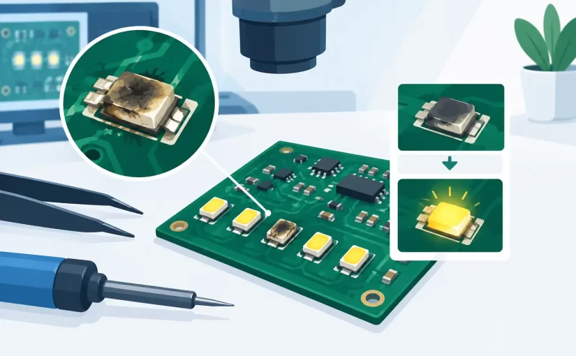
A dark LED does not prove that the LED itself has failed. In this LED failure analysis example, a status indicator on a 12 V control PCB remains off while the rest of the board operates normally. The fault could be an open LED junction, a cracked solder joint, a failed current-limiting resistor, a missing supply rail, or a transistor that is no longer sinking current. Efficient repair depends on separating those possibilities with measurements rather than replacing parts by assumption.
The board-level symptom
The PCB is a motor-control module with a green LED labeled RUN. When 12 V is applied, the microcontroller starts, the output relay responds, and the 5 V logic rail measures correctly. The RUN LED remains dark under conditions where it should be illuminated.
The relevant circuit is conventional: 12 V feeds a 1 kΩ SMD resistor, then the LED anode. The cathode connects to the collector of an NPN transistor controlled by the microcontroller. When the controller drives the transistor on, current flows through the resistor and LED to ground.
The LED package is a 0603 green device. Its compact size matters because an ordinary multimeter probe can easily slip across adjacent pads, damage the package, or create a misleading reading through a parallel circuit path. Start by documenting the PCB reference designators and circuit orientation before applying probes.
Step 1: Inspect before energizing
A close visual inspection often identifies the shortest path to the fault. Examine the LED lens for discoloration, cracking, or a burned spot. Check whether the resistor has changed color or whether its solder fillets show a ring crack. On production boards, compare the suspect assembly against a known-good unit under the same magnification and lighting.
In this case, the LED lens looks normal. The resistor has no visible heat damage. However, the LED cathode pad has a slightly dull solder joint, suggesting possible mechanical stress or incomplete wetting. That is useful evidence, but it is not enough to justify rework. A joint may look imperfect and still make a low-resistance connection.
Also inspect the board for contamination around the LED circuit. Residue, moisture, and conductive debris can alter high-impedance control nodes, although they rarely stop a normally driven indicator LED unless the circuit has already been compromised.
Step 2: Measure the circuit while powered
With power applied and the RUN condition active, measure the voltage across the LED first. This is more informative than measuring from one LED terminal to chassis ground without knowing the circuit topology.
The anode measures 11.96 V. The cathode measures 11.91 V. The resulting LED voltage is only 0.05 V, far below the expected forward voltage of approximately 2.0 V for a green LED at normal indicator current.
That result narrows the diagnosis. Both LED terminals are near the 12 V supply, so the low-side transistor is not pulling the cathode toward ground. The LED may still be open, but an open LED alone would normally leave the cathode behavior dependent on the transistor circuit and leakage paths. The immediate fault area is now the transistor drive path, the transistor itself, or an open connection between the LED cathode and transistor collector.
Next, measure the resistor voltage drop. It reads 0.04 V. A 1 kΩ resistor with 0.04 V across it carries about 0.04 mA, which is effectively no LED operating current. The supply side of the indicator circuit is present, but the current loop is incomplete.
Why powered measurements come first
An in-circuit diode test can be valuable, but it does not show whether the controller is commanding the LED on. Powered voltage checks establish which part of the current path is missing: source voltage, current limiting, LED forward drop, switching action, or return path.
For boards with high-density SMD layouts, use probes that provide controlled contact pressure and clear tip placement. Tweezer-style instruments and fine test probes reduce the chance of bridging nearby pads. Do not use an LCR measurement function on an energized circuit. Power must be removed before resistance, capacitance, inductance, or semiconductor test measurements are made.
Step 3: Verify the switching transistor
The transistor base measures 0.02 V while the RUN signal is expected to be active. The collector is near 12 V, and the emitter is at ground. This confirms that the transistor is off, but does not yet identify whether the transistor is defective or simply not receiving drive.
Tracing the base circuit reveals a 10 kΩ resistor between a microcontroller output and the transistor base. The microcontroller pin measures 0.01 V. The board firmware is running, so the next question is whether the controller is intentionally holding the LED off or whether the output has failed.
A comparison board provides the answer. On the known-good board, the same pin measures 3.28 V under the RUN condition, the transistor base measures 2.61 V, and the LED cathode measures 0.18 V. The expected electrical states are now documented.
At this point, replacing the LED would be premature. The failed board has a logic-level drive problem upstream of the LED circuit. A firmware state, damaged microcontroller output, broken trace, failed pull-down network, or input condition preventing RUN status could all produce the same dark LED.
Step 4: Isolate the load from the control path
Power is removed and the LED circuit is checked with a diode-test function. Probing directly across the LED in the forward direction produces a dim green glow and a forward voltage of 2.08 V. Reversing the probes shows overload. The LED junction is functional.
The 1 kΩ resistor measures 998 Ω after confirming that the surrounding circuit does not create a parallel path significant enough to affect the result. For a resistor this close to nominal value, the current-limiting component is not the cause of the missing light.
The transistor is then checked out of circuit because in-circuit junction readings are influenced by the base resistor and microcontroller protection structures. Its base-emitter and base-collector junctions show normal diode behavior, while collector-emitter remains nonconductive with no base drive. The transistor is also functional.
The fault is ultimately traced to a lifted trace at the microcontroller output pad, caused by earlier rework near a connector. Under magnification, the trace appears intact. Continuity testing between the controller pin and the base resistor pad, however, reads open. A fine jumper repair restores the logic drive, and the LED returns to normal operation.
What this LED failure analysis example proves
The visible symptom was a dark LED, but the failed part was neither the LED nor its resistor or transistor. The repair depended on following the current path and signal path separately.
The current path was 12 V, resistor, LED, transistor, and ground. The signal path was microcontroller output, base resistor, transistor base, and collector current. Measuring both paths prevented a common repair error: replacing the most visible component instead of locating the missing electrical condition.
A practical sequence for most indicator circuits is visual inspection, powered voltage measurements, comparison with a known-good board where available, then unpowered component and continuity tests. The order may change when safety, conformal coating, inaccessible nodes, or a complex multiplexed LED driver is involved. For RGB LEDs, matrix displays, and constant-current drivers, the controller timing and driver-enable signals must also be evaluated.
Measurement details that improve repeatability
Record the board supply voltage, operating mode, ambient condition, and probe locations with every diagnosis. A measured 2.0 V LED drop has little meaning unless the technician knows the LED color, current, drive topology, and whether the circuit is static or pulse-width modulated.
For component-level checks, instruments designed for direct SMD contact can reduce handling time and measurement uncertainty. A calibrated handheld LCR meter such as a Siborg Smart Tweezers or LCR-Reader can identify a resistor, capacitor, or inductor directly at the board level when the circuit permits a valid in-circuit reading. Semiconductor checks still require attention to parallel paths and applied voltage conditions.
If the LED is driven with PWM, a standard digital multimeter may display an averaged voltage that obscures the actual switching behavior. An oscilloscope measurement at the LED cathode or driver output can show whether pulses are present, their amplitude, duty cycle, and frequency. A signal that looks incorrect on a meter may be entirely normal under PWM control, while a flat line can immediately expose a missing enable or clock condition.
The useful repair habit is simple: do not ask only, “Is the LED bad?” Ask where voltage stops, where current stops, and whether the control signal is commanding the circuit to operate. That approach scales from one 0603 status LED to dense production assemblies where every unnecessary replacement adds cost and risk.