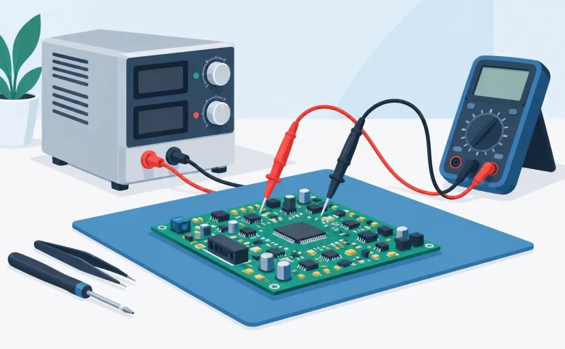
A board that will not boot is not necessarily a logic-board failure. A missing 3.3 V rail, a 12 V line that collapses under load, or excessive ripple from one degraded capacitor can produce symptoms that look like firmware, communication, or processor faults. Effective power supply diagnosis starts by treating every rail as a measurable system: source, control circuit, energy-storage components, distribution path, and load.
For PCB repair, the objective is not simply to find a voltage that reads low. It is to determine whether the supply is failing to start, regulating incorrectly, shutting down for protection, or being pulled down by a downstream fault. That distinction prevents unnecessary component replacement and reduces the risk of damaging a board during troubleshooting.
Start Power Supply Diagnosis With a Safe Baseline
Before applying power, identify whether the circuit is isolated from the AC mains and whether hazardous voltages can remain stored after shutdown. Primary-side capacitors in offline power supplies can retain a dangerous charge. Use the correct safety procedures, discharge method, isolation equipment, probe ratings, and personal protective practices for the equipment under test. Do not connect an earth-referenced oscilloscope ground clip to a non-isolated mains-referenced primary circuit.
With power removed, inspect the board under magnification. Look for cracked solder joints at transformers, inductors, power connectors, MOSFETs, and high-current resistors. Darkened PCB material, electrolyte residue, lifted pads, and discolored components are useful evidence, but absence of visible damage proves little. Many failed ceramic capacitors, switching controllers, and semiconductors show no external sign.
Record the expected rails from the schematic, board markings, connector labels, or a known-good unit. Include the nominal voltage, allowable tolerance where available, sequence requirements, and whether a rail is always present or enabled only after a control signal changes state. A 5 V standby rail can be healthy while the main 12 V converter remains disabled. Testing only the output connector without checking enable and feedback signals can lead to the wrong conclusion.
Separate Input, Converter, and Load Faults
A practical diagnostic sequence moves from the source toward the load. First confirm that the input reaches the power circuit. Check fuses, connectors, reverse-polarity devices, input filters, bridge rectifiers, and protection MOSFETs. A fuse that has opened is evidence of excessive current, not usually the root cause. Measure for a shorted bridge, MOSFET, or bulk capacitor before fitting a replacement.
Next, test the output rail with power off. Resistance-to-ground measurements are fast screening tests, particularly when compared with a known-good board. However, low resistance is not automatically a short. Processor cores, FPGA rails, and high-current low-voltage supplies may normally measure only a few ohms or less. Compare readings, understand the rail’s intended load, and watch whether the resistance rises as capacitors charge from the meter’s test current.
When a rail has an abnormal low-resistance reading, inject a controlled low voltage using a current-limited bench supply. Start well below the rail’s nominal voltage and set a conservative current limit. Thermal imaging, freeze spray, voltage-drop measurements, or careful fingertip checks where safe can help locate the component dissipating power. Current injection is effective for locating shorted MLCC capacitors and failed ICs, but excessive injection voltage can forward-bias semiconductor junctions and create misleading heat paths.
If the output is not shorted, apply normal power and measure the rail at the converter output, then at the load. A healthy voltage at the regulator but a low voltage at an IC pin points to an open fuse, ferrite bead, connector, trace, or damaged via. Conversely, an output that rises briefly and drops may indicate overcurrent protection, undervoltage lockout, a missing feedback path, or a startup problem.
Measure More Than DC Voltage
A digital multimeter is essential, but its DC display is only one part of the evidence. A rail may read 5.00 V while carrying enough ripple to reset digital circuitry or corrupt analog measurements. Check the AC component with an oscilloscope using a short ground spring or a very short ground connection at the output capacitor. A long probe ground lead acts as an antenna and can display ringing that is largely measurement artifact.
Evaluate ripple amplitude, switching frequency, burst behavior, and transient response. Periodic sawtooth ripple may suggest insufficient capacitance or elevated ESR. High-frequency spikes can result from poor layout, failed ceramic bypass capacitors, diode recovery effects, or probing technique. A converter that repeatedly starts and stops often produces a low-frequency burst envelope rather than a steady switching waveform.
For switching regulators, examine the controller’s VIN, enable, soft-start, feedback, gate-drive, and switching-node signals as the design permits. The expected waveform depends on topology. In a buck converter, a switching node that remains static may indicate that the controller is disabled, not powered, in thermal shutdown, or protecting against a fault. Gate-drive activity with no usable output directs attention toward the MOSFETs, inductor, catch diode or synchronous device, and output network.
Avoid interpreting waveform shape without reference to the circuit topology and probe bandwidth. A clean-looking switching node does not prove correct regulation, while a visually noisy node may be normal in a fast converter. The useful question is whether the waveform supports the specified output voltage, current capability, ripple limit, and startup behavior.
Capacitors, ESR, and In-Circuit Measurements
Capacitor failure remains common in power supply repair, but capacitance alone is an incomplete test. An electrolytic capacitor can retain a plausible capacitance value while its ESR has risen enough to cause startup instability or output ripple. ESR measurement is particularly useful on output filters, bulk capacitors, and control-loop compensation networks where low impedance matters.
In-circuit ESR testing is fastest when the surrounding circuit does not provide a parallel low-impedance path. Compare suspect capacitors in the same rail or against a known-good assembly when possible. A reading that appears low may be influenced by parallel ceramic capacitors, semiconductors, or the load. Remove one lead only when the in-circuit result conflicts with the rest of the evidence.
Small ceramic capacitors require a different approach. Their typical ESR is already very low, and their most damaging failure mode is often a partial or direct short. Resistance-to-ground comparison, current injection, and thermal methods usually provide more useful fault isolation than capacitance measurement alone. For loose components or isolated parts, an LCR meter can verify capacitance, dissipation factor, inductance, or resistance at a test frequency relevant to the circuit.
On dense boards, tweezer-style instruments reduce the time required to verify SMD resistors, capacitors, inductors, and diode paths directly at the component. Instruments such as Siborg Smart Tweezers can support rapid in-circuit screening, but measurement results must still be interpreted in the context of parallel paths and circuit bias conditions.
Common Failure Patterns and What They Mean
Certain symptom patterns narrow the search quickly. No standby output usually points toward the input section, auxiliary supply, startup resistor network, controller bias, or primary switching stage. A correct standby rail with no main output shifts attention to enable logic, optocoupler or feedback circuits, secondary protection, and the main converter.
An output that is correct with no load but collapses when connected can indicate a weak capacitor, current-limit threshold issue, insufficient input energy, damaged inductor, or excessive downstream load. Test with a known resistive load when practical. This separates a supply that cannot deliver rated current from a board that is demanding abnormal current.
An output that is consistently high requires prompt attention. Open feedback resistors, failed reference devices, optocoupler faults, broken sense connections, and controller failures can all remove regulation. Do not leave sensitive loads connected while investigating an overvoltage condition. A voltage that is slightly low may be benign at the regulator output but unacceptable at a remote load after cable and connector losses, especially on high-current rails.
Intermittent faults deserve temperature and mechanical testing. Gentle board flexing, connector movement, localized heat, and controlled cooling can expose fractured joints, marginal capacitors, and temperature-sensitive semiconductors. Document each response rather than relying on a single successful power-up.
Build Evidence Before Replacing Parts
The fastest repair workflow is evidence-driven: verify input, identify the affected rail, check for abnormal resistance, confirm control and enable conditions, measure ripple and switching behavior, then isolate the defective stage. Replacing all capacitors or every semiconductor in the vicinity may occasionally restore operation, but it sacrifices diagnostic confidence and can introduce assembly defects.
Keep measurements with the repair record, including rail voltage, ripple, input current, component values, and test conditions. This is especially useful in production, field service, and recurring equipment faults, where a trend in ESR, startup time, or short-circuit current can reveal a design or environmental issue.
A power supply is working only when it starts predictably, regulates within specification, supports its intended load, and remains stable through normal transients. Measure those conditions methodically, and the fault usually becomes much smaller than the board that first arrived on the bench.