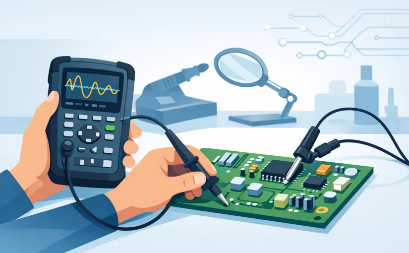
A switching regulator that looks normal on a multimeter can still be the source of a board failure. It may start, collapse under load, and restart in a few microseconds. A handheld oscilloscope for PCB repair makes that behavior visible at the point where the fault occurs: on the rail, gate drive, clock line, reset signal, or data bus.
For field technicians and bench repair specialists, portability is only one part of the decision. The useful instrument is the one that can capture intermittent events, work safely around grounded equipment, and reach densely populated assemblies without turning the probe into another source of error. Bandwidth, triggering, probe selection, input configuration, and measurement workflow matter more than an impressive headline specification.
What a Handheld Oscilloscope Adds to PCB Repair
A digital multimeter establishes the basics quickly: Is the fuse open? Is a rail present? Is there a short between power and ground? But a meter reports an averaged or slowly updated value. It cannot show excessive ripple on a 3.3 V rail, a missing enable pulse, ringing at a MOSFET gate, or a clock signal that disappears after startup.
An oscilloscope adds time-domain evidence. It lets the technician compare a known-good waveform with a suspect one, determine whether a rail is stable during a load transition, and establish the sequence of events around a fault. On multilayer boards, this often narrows troubleshooting from a large power or control section to a few components.
It is not a replacement for component measurement. A waveform can indicate that an output capacitor has lost effective capacitance or developed high ESR, but an LCR or ESR measurement is needed to evaluate the component directly. Likewise, a scope may reveal a distorted logic line, while a meter, LCR instrument, or tweezer-style SMD tester identifies the failed resistor, capacitor, diode, or inductor. Efficient PCB repair uses these tools in sequence rather than expecting one instrument to answer every question.
Selecting a Handheld Oscilloscope for PCB Repair
Start with the signals you actually service
For audio circuits, basic microcontroller boards, low-speed sensor interfaces, and many linear power supplies, moderate bandwidth is generally sufficient. Switching supplies, motor-control circuitry, fast digital interfaces, RF-adjacent control circuits, and modern embedded boards place greater demands on the instrument.
A practical rule is to choose bandwidth substantially above the fundamental frequency of interest because waveform edges contain high-frequency content. A 100 kHz switching converter does not require only 100 kHz of bandwidth if the diagnostic question concerns switch-node ringing, gate-edge behavior, or high-frequency ripple. At the same time, paying for very high bandwidth is not automatically useful if the supplied probe, sample rate, and grounding method limit the measurement.
Sample rate and record length should be evaluated together. A high sample rate helps preserve short events and sharp transitions. Adequate memory depth allows the instrument to capture a longer startup sequence, then zoom into the brief interval where a power rail drops or a controller resets. Instruments with limited record length can force a choice between seeing fine detail and seeing enough time before the fault.
Triggering determines whether you catch the failure
Stable repetitive waveforms are easy to display. The difficult repairs involve events that occur once, occur after several seconds, or appear only when a board warms up or draws current. Edge triggering is the minimum requirement, but a handheld scope becomes much more useful when it provides single-shot capture, adjustable trigger levels, pre-trigger viewing, and pulse-width or timeout triggering.
Consider a board that powers up, flashes an indicator, and shuts down. Triggering on the falling edge of the main rail may capture the supply collapse, but triggering on an enable line or power-good signal may show which section acted first. This distinction prevents the common mistake of replacing a regulator when the actual cause is a downstream overload or a supervisory circuit.
Two channels are often the practical minimum
One channel can confirm whether a signal exists. Two channels let the technician establish cause and effect. You can compare an input rail with an output rail, gate drive with switch-node response, reset with clock activity, or a reference voltage with a feedback node.
Four channels are valuable for more involved digital or power-electronics work, but channel count has trade-offs in cost, size, interface complexity, and battery life. For general field repair, a capable two-channel instrument with dependable triggering is frequently more productive than a nominal four-channel model with limited controls or memory.
Probe Quality and Grounding Are Part of the Measurement
The scope is only as reliable as the connection to the board. Standard 10:1 passive probes are useful because they reduce circuit loading and support higher voltage ranges than a direct 1:1 connection. For low-voltage signals, a 1:1 probe can improve sensitivity, but its capacitance may distort fast edges or affect a high-impedance node.
Probe tips, ground springs, grabbers, and fine accessories deserve the same attention as the instrument itself. A long ground lead can form an inductive loop that displays ringing that is partly created by the measurement setup. When examining a fast switching node, use the shortest practical ground connection and verify suspicious ringing with an improved probing arrangement before diagnosing a component fault.
Grounding also has a safety dimension. Many handheld oscilloscopes have BNC ground references tied together, and some are tied to protective earth when charging or connected to another grounded device. Connecting a ground clip to a non-isolated mains-referenced node can create a short circuit and damage the board, probe, or instrument. Battery operation does not automatically make every input safe for every measurement.
Read the instrument’s input ratings and common-mode limits. For offline power supplies, mains-connected motor drives, and other high-energy circuits, use an appropriately rated differential probe or an isolation method designed for the task. Never treat a handheld instrument as an assumption of isolation.
Screen, Controls, and Data Capture Affect Repair Speed
A compact scope must remain usable with a board in one hand and a probe in the other. A bright display, clear status indicators, responsive timebase controls, and physical controls for frequently adjusted settings reduce setup time. Touch-only interfaces can be efficient for review, but they are less convenient when gloves, contamination, or awkward working angles are involved.
Automatic measurements are helpful for frequency, duty cycle, peak-to-peak voltage, and rise time, provided the waveform is clean enough for the measurement algorithm. Cursors remain essential when examining noisy or irregular waveforms. Saving screenshots and waveform records is useful for repair documentation, remote support, production failure analysis, and comparing a repaired board against its original condition.
For technicians who already use compact component analyzers, an integrated workflow can reduce tool changes. Siborg Systems instruments that combine direct SMD measurement with oscilloscope and Analog Signature Analysis capabilities are particularly relevant when a waveform observation needs to be followed immediately by component-level testing on a populated board.
A Disciplined Scope Workflow for Fault Finding
Begin with the board’s power architecture. Measure the input supply, then check major rails for correct DC level, ripple, startup behavior, and response to load. Probe enables, power-good outputs, and reset signals before moving into complex digital sections. These signals often reveal whether the fault is power-related, supervisory, or downstream.
Next, compare nodes rather than examining each one in isolation. A regulator output that falls at the same time as an enable signal points in a different direction than an output that falls while enable remains asserted. A clock that is present until reset drops suggests a control problem; a missing clock with reset high suggests an oscillator, crystal, supply, or processor issue.
Use known-good references when available. A matching board, a serviceable channel on the same assembly, or a documented waveform can be more valuable than a generic expectation. PCB repair is rarely about whether a waveform looks aesthetically clean. It is about whether its amplitude, timing, noise, and response match the circuit’s operating requirements.
When a Handheld Scope Is the Right Tool
A handheld instrument is well suited to field service, production-floor diagnostics, equipment maintenance, mobile repair, and benches where space is limited. It is especially effective for checking low- and medium-voltage control electronics, power rails, startup sequences, PWM signals, serial activity, and intermittent faults.
A bench oscilloscope may still be the better choice for demanding high-speed digital analysis, extensive protocol decoding, deep acquisition requirements, or complex multi-channel work. The right decision depends on the circuits under service and the consequences of missing a brief event.
Choose the handheld scope around the failure modes you need to capture, then invest equal care in probes, grounding, and component-test capability. A clear waveform is useful, but the repair moves faster when that waveform leads directly to a testable hypothesis at the component level.