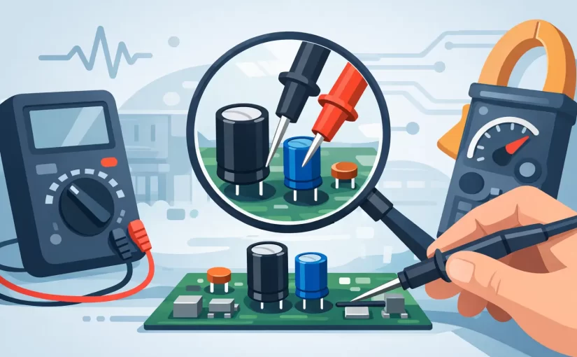
A capacitor that looks normal can still be the reason a power rail will not start, an audio channel distorts, or a switching supply pulses under load. The ability to test capacitors without desoldering can shorten fault isolation dramatically, especially on densely populated PCBs where lifting a pad creates its own repair risk. The limitation is straightforward: an in-circuit measurement is a measurement of the capacitor plus every conductive path connected around it. Good troubleshooting depends on knowing when that reading is useful and when the circuit is masking the fault.
Test Capacitors Without Desoldering: What Is Possible?
In-circuit capacitor testing works best as a screening and comparison method. It is highly effective for finding an obvious shorted ceramic capacitor, a dried-out electrolytic with elevated ESR, or a part whose measured value differs substantially from identical capacitors on the same board.
It is less reliable when a capacitor is connected in parallel with other capacitors, across a low-resistance supply rail, or adjacent to semiconductor junctions that begin to conduct at the meter’s test voltage. In these cases, the displayed capacitance may be higher than the component’s marked value, the ESR may appear lower than it really is, or the meter may identify a different component type altogether.
A useful rule is to treat an in-circuit result as evidence, not a final verdict. A reading that clearly indicates a short, open circuit, or severe ESR problem is actionable. A reading that appears plausible but does not match the symptom may require comparison measurements, schematic review, or isolation of one capacitor lead.
Start With a Safe, De-Energized Board
Do not measure capacitance or ESR on a powered circuit. Remove input power, disconnect batteries where practical, and verify that stored energy has been discharged. Large electrolytic capacitors in power supplies, motor drives, flash circuits, and high-voltage equipment can retain hazardous voltage after the equipment is unplugged.
Use a properly rated discharge method for the circuit rather than shorting capacitor terminals with a screwdriver. After discharge, confirm the voltage with a multimeter before placing an LCR meter, ESR meter, or test tweezers on the board. This protects the instrument as well as the operator.
The board should also be electrically quiet. USB connections, backup batteries, supercapacitors, and charged secondary rails can keep portions of a PCB energized when the main supply is removed. A capacitance reading taken on a partially powered rail is not valid and can damage a sensitive handheld meter.
Choose the Measurement That Matches the Failure Mode
Capacitance alone does not describe capacitor health. A part can remain close to its nominal capacitance while its ESR has risen enough to cause ripple, poor regulation, startup failure, or instability in a switching converter. Conversely, a ceramic capacitor can fail as a low-resistance short while an ESR reading is not the fastest way to identify it.
Capacitance Measurement
Capacitance mode is useful for detecting an open capacitor, a large loss of capacitance, or an unexpected value in a simple circuit. It is most dependable when the component has limited parallel loading. Small SMD capacitors are particularly susceptible to misleading readings because nearby IC pins, bypass capacitors, and supply planes may dominate the result.
For polarized electrolytic capacitors, compare the measured value with the marked nominal capacitance and tolerance. A 10% or 20% deviation may be normal, depending on the capacitor series and test conditions. A measurement that is dramatically low, unstable, or absent deserves further investigation.
ESR Measurement
ESR testing is often the more productive in-circuit method for aluminum electrolytic and polymer capacitors. It can reveal degradation that basic capacitance mode misses. In low-voltage power circuits, a high ESR reading relative to identical nearby capacitors is a strong fault indicator.
ESR is frequency-dependent, so meaningful results require appropriate test conditions. A meter operating at a higher test frequency can better reflect behavior in switching regulators and decoupling networks than a low-frequency capacitance measurement. However, do not compare readings from different meter models or test frequencies as though they were directly interchangeable.
LCR Measurement and Impedance
An LCR meter provides more diagnostic context by measuring capacitance, resistance, inductance, impedance, and phase according to the selected mode. This is valuable when identifying small SMD parts or checking whether an apparent capacitor is actually being influenced by another component path.
For PCB work, test frequency matters. A component that appears acceptable at 1 kHz may behave differently at 100 kHz or 250 kHz, particularly in high-frequency decoupling or switching applications. The right frequency depends on the circuit’s operating range and the failure symptom, not simply on the capacitor’s printed value.
A Practical In-Circuit Test Procedure
First, inspect the board under adequate magnification. Look for cracked MLCCs near board edges, discolored electrolytic sleeves, lifted terminations, leaked electrolyte, corroded vias, and heat-stressed areas around regulators. Visual inspection will not find every failure, but it helps establish where measurements should begin.
Next, identify the capacitor’s circuit role. A bulk input capacitor, output filter capacitor, local bypass capacitor, timing capacitor, and AC-coupling capacitor should not be evaluated by the same expectations. A shorted bypass capacitor on a 3.3 V rail produces a different signature than a high-ESR output capacitor in a buck converter.
With the board discharged, place the probes directly on the capacitor terminations. Tweezer-style probes are especially effective for small two-terminal SMD components because they minimize contact with adjacent pads. Keep probe pressure light. Excess force can slip across neighboring pads or fracture a small ceramic capacitor.
Record the result, then compare it with similar components in the same design. If a board has several identical 10 µF decoupling capacitors on the same rail, a single part with distinctly lower impedance, unusually high ESR, or an inconsistent capacitance result is a useful suspect. Comparative testing often provides more value than comparing every reading to a datasheet limit.
If the meter reports a short or very low resistance, confirm the finding from both sides of the component and at another point on the rail. A capacitor may be healthy while a downstream IC, diode, or damaged power stage is causing the low-resistance condition. The capacitor is electrically in parallel with that fault.
Interpreting Common In-Circuit Results
A near-zero resistance or continuity indication across a ceramic capacitor can point to a shorted MLCC, but it can also be normal on a low-impedance core-voltage rail. Compare the rail to a known-good board if available, and use thermal methods or controlled current injection when the short cannot be localized by meter readings alone.
A capacitance value much higher than the printed marking usually means parallel capacitance is present. This does not prove the tested part has drifted upward. In a decoupling bank, the meter may be reading several capacitors at once.
A capacitance value lower than expected can be more meaningful, but only after accounting for circuit paths and test frequency. A regulator feedback network, resistor divider, or semiconductor junction may interfere with the measurement. If several identical capacitors measure similarly low, the reading likely reflects the circuit rather than a batch of failed parts.
An elevated ESR result on one electrolytic compared with matching parts is often a strong indication of deterioration. Confirm capacitor polarity, rated voltage, temperature class, and location before replacement. A capacitor positioned beside a heatsink or switching transistor may age faster than visually identical parts elsewhere on the PCB.
When You Must Lift One Lead
Desoldering is necessary when the circuit makes the result ambiguous and the repair decision has material consequences. Lift one lead, or remove the component entirely, when a suspected capacitor is connected directly across a low-resistance rail, paralleled with multiple capacitors, or tied to active semiconductor circuitry that distorts the measurement.
This is also the right approach for final verification in quality control, failure analysis, and repair documentation. In-circuit testing identifies candidates quickly; isolated testing establishes the component’s actual electrical parameters.
For technicians handling dense SMD assemblies, a precision handheld LCR instrument with tweezer probes can reduce the time spent moving between test points. Siborg Smart Tweezers instruments are designed for direct component contact and can support fast identification and measurement of small board-level parts where conventional test leads are less precise.
The most productive workflow is not to desolder every capacitor preemptively or to trust every in-circuit number without question. Measure the circuit safely, compare like components, use ESR and frequency-aware LCR data where the failure mode demands it, and isolate the part only when the board cannot provide a clear answer. That approach protects pads, preserves troubleshooting time, and keeps each measurement tied to a defensible repair decision.