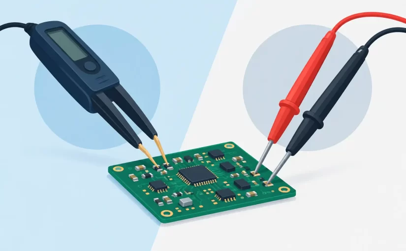
A tweezer meter versus probes decision is usually made at the point where a technician is trying to contact a 0402 resistor between two ICs without slipping onto an adjacent pad. Both interfaces can produce valid measurements. The difference is how quickly, repeatably, and safely they make contact with the component under test.
For loose through-hole parts, conventional test leads remain practical. For populated boards with dense SMD layouts, a handheld LCR meter with tweezer electrodes can reduce setup time substantially. The right choice depends on component size, circuit conditions, required measurement mode, and whether the work is troubleshooting, incoming inspection, production verification, or design validation.
Tweezer Meter Versus Probes: The Core Difference
A tweezer meter integrates the measurement terminals into two insulated, spring-loaded tips. The user picks up a loose SMD component or contacts its two terminals directly on a PCB. The meter applies its test signal, identifies the component type where supported, and displays the relevant parameter such as resistance, capacitance, inductance, impedance, or ESR.
Conventional probes separate the meter from the contact points through flexible leads. This is useful when test points are far apart, the component is physically large, or the circuit requires a specific probing geometry. A digital multimeter probe pair is also familiar, inexpensive, and adaptable to voltage, current, continuity, and general resistance work.
The practical distinction is not simply speed. Tweezer electrodes place the measuring instrument at the component interface, minimizing lead movement and making two-terminal contact intuitive. Probe-based measurements are more flexible, but the leads, probe pressure, and operator hand position introduce more variables. On a crowded PCB, those variables affect both workflow and confidence in the reading.
Where a Tweezer Meter Has a Clear Advantage
Small SMD components and dense layouts
A 0201, 0402, or 0603 component is difficult to hold and test with standard pointed probes. Even when contact is possible, the operator may need one hand to stabilize the board and another to manage both probes. Tweezer-style electrodes contact both ends from above, which is typically faster for loose components and board-level work.
This geometry also reduces the chance of bridging adjacent pads. That matters when checking resistor networks, decoupling capacitors, RF passives, and small inductors located close to fine-pitch packages. Good tip alignment and controlled spring force help maintain contact without excessive pressure on fragile pads.
LCR and ESR measurements at useful frequencies
A multimeter resistance range is not an LCR measurement. It may identify an open or shorted part, but it generally cannot characterize capacitance, inductance, dissipation factor, quality factor, or ESR with the same test conditions as a dedicated LCR instrument.
For capacitor troubleshooting, test frequency matters. ESR and impedance behavior can change significantly with frequency, capacitor technology, and capacitance value. A meter capable of 100 kHz or 250 kHz testing can provide more relevant data for switching-power, high-frequency decoupling, and low-ESR capacitor applications than a basic low-frequency measurement.
Siborg Smart Tweezers instruments are designed around this direct-contact workflow, combining SMD-accessible electrodes with professional LCR measurement functions. Advanced models add capabilities such as Bluetooth connectivity, oscilloscope operation, and Analog Signature Analysis for technicians who need more than a single numeric reading.
Repetitive inspection work
Speed becomes more valuable when the same action is repeated hundreds of times. During incoming inspection, rework verification, or fault isolation, an operator can move from component to component with fewer lead placements and less repositioning. The gain is not only seconds per reading. It is a more consistent contact method across the entire test sequence.
For quality-control environments, repeatability also depends on instrument accuracy, calibration status, test frequency, and the selected equivalent circuit mode. A NIST-traceable calibration certificate provides documentation that a measurement tool has been checked against defined standards, but it does not eliminate the need for a sound test method.
Where Conventional Probes Remain the Better Tool
Voltage, current, and distributed circuit testing
Tweezer meters are optimized for two-terminal component measurements. They are not a replacement for multimeter probes when measuring supply rails, voltage drops, logic levels, current, or continuity across distant points. A technician troubleshooting a 12 V power input, checking a transistor bias voltage, or tracing a ground fault needs the reach and flexibility of conventional leads.
Probe accessories can also be selected for specialized work. Fine needle probes access vias and test pads. Hook clips maintain contact during long observations. Kelvin clips and four-wire fixtures improve low-resistance measurements by reducing the effect of lead and contact resistance. These are applications where ordinary tweezer tips may not provide the required connection or measurement configuration.
Large parts and awkward mechanical locations
Radial capacitors, power resistors, chassis-mounted devices, and components in recessed locations may be easier to reach with leads. Probe tips can approach from different angles, while clips can remain attached without the operator holding the meter in position.
The same applies when the component terminals are farther apart than the opening of the tweezer electrodes. A flexible lead set is not less professional in this situation. It is the appropriate interface for the mechanical layout.
Measurements requiring stable hands-free contact
If a test requires watching a value while flexing a cable, heating a board area, cycling power, or adjusting a circuit, clips and probes may be more suitable. The instrument can remain connected while the technician performs the next diagnostic step. Tweezers excel at rapid spot checks, not every extended observation.
Accuracy Depends on More Than the Contact Style
It is tempting to assume that tweezers are automatically more accurate because they are closer to the component. In practice, basic accuracy is determined by the instrument specification, calibration, range, test frequency, and measurement method. Contact quality determines whether that capability reaches the device under test.
For low resistance, oxidation, solder residue, and weak tip pressure can add meaningful error. For small capacitance and inductance values, board parasitics, lead length, and nearby copper can influence readings. Open and short compensation, when available, should be performed with the actual test accessories and measurement conditions in mind.
Probe leads can add inductance and capacitance, particularly at higher test frequencies. That does not make them unusable. It means the technician should account for fixture effects, keep leads short where possible, and use the correct compensation procedure. Dedicated Kelvin methods are preferable when measuring very low resistance where a two-wire setup would include lead resistance.
In-Circuit Testing Requires Judgment
Neither a tweezer meter nor probes can guarantee that an in-circuit reading represents only the selected component. Parallel resistance paths can lower a resistance reading. Other capacitors connected to the same node can increase apparent capacitance. Semiconductor junctions and energized circuits can produce readings that are misleading or unsafe for the instrument.
Power should normally be removed and stored energy discharged before passive-component testing. Then compare the measurement to the schematic, board layout, known-good board data, and the expected behavior of surrounding circuitry. A suspicious in-circuit value may justify lifting one lead or removing the component for confirmation.
Tweezer meters make it easier to gather fast comparative readings across a board. Probes may be better when tracing the connected network that explains why those readings differ. Effective repair work commonly uses both tools in sequence.
Choosing the Right Interface for the Job
Choose a tweezer meter when the immediate task is identifying or verifying small two-terminal SMD components, especially on populated boards. It is particularly effective when LCR or ESR data is needed quickly and when repeatable contact matters more than long reach.
Choose conventional probes when the task involves voltage, current, distant nodes, large components, hands-free clips, or specialized four-wire connections. They remain essential bench tools, not an older method displaced by tweezers.
For technicians who regularly repair compact electronics, the most efficient bench is not built around a single interface. Keep probes available for circuit-level diagnosis, then use a calibrated tweezer meter to make direct component checks where speed, access, and LCR performance determine the next repair decision.