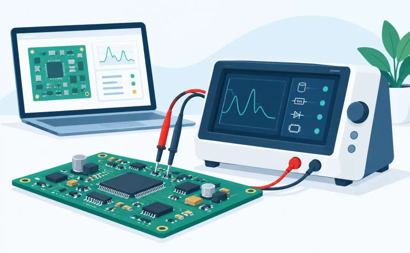
A 0402 capacitor that looks identical to its neighbors can stop a power rail, shift a timing circuit, or turn a working board into an intermittent fault. Component analyzers reduce the time between finding that suspect part and obtaining a meaningful measurement. For PCB repair, production inspection, and design verification, the useful question is not simply whether an instrument can display capacitance or resistance. It is whether it can make a repeatable measurement at the component, under the conditions that matter.
What Component Analyzers Actually Do
Component analyzers are instruments used to identify and characterize electronic components by measuring values such as resistance, capacitance, inductance, impedance, ESR, diode forward voltage, continuity, and semiconductor junction behavior. The term covers several instrument categories, including handheld LCR meters, ESR meters, digital multimeters, transistor testers, curve-tracing tools, and analog signature analyzers.
A general-purpose multimeter remains essential, but it is not always the fastest or most informative tool for component-level work. Its capacitance range may not characterize a low-value capacitor well, its resistance mode may not distinguish a resistor from a semiconductor path, and its diode mode cannot report the ESR of an electrolytic or ceramic capacitor. A dedicated analyzer applies a controlled test signal and interprets the component response using the appropriate measurement model.
That distinction becomes more significant with surface-mount devices. Fine-pitch boards place parts close together, and conventional test leads can slip, bridge adjacent pads, or add enough contact resistance and inductance to affect low-value measurements. Tweezer-style instruments address the physical access problem directly by combining probes and measurement electronics in a compact handheld format.
Measurement Is Only Useful in Context
An instrument can report a precise number and still lead to the wrong service decision if the measurement conditions do not match the component or circuit. Engineers and technicians should consider test frequency, test voltage, measurement mode, contact quality, and whether the component is measured in or out of circuit.
Test frequency changes the result
Capacitors and inductors are frequency-dependent devices. A capacitor specified at 1 kHz may behave very differently at 100 kHz, while an inductor intended for a switching converter requires characterization nearer its operating range. At higher frequencies, lead inductance, dielectric loss, winding resistance, and parasitic capacitance become more visible.
For this reason, an LCR instrument with only a low test frequency is not interchangeable with a model offering 100 kHz or 250 kHz testing. High-frequency capability is especially useful when checking low-value capacitors, RF-related parts, small inductors, ferrite beads, and power-stage components. It does not mean that the highest frequency is always correct. The appropriate setting depends on the component specification and the failure mechanism being investigated.
ESR requires more than capacitance
A capacitor can measure close to its marked capacitance and still be unsuitable for service. Elevated equivalent series resistance creates heat, ripple, voltage drop, and unstable regulator behavior. This is common in aging aluminum electrolytics, but ESR also matters in polymer capacitors and some high-current ceramic applications.
An ESR measurement is most informative when compared with the expected value for the capacitor type, size, voltage rating, and application. A single universal pass/fail threshold is not technically sound. Very low ESR is normal for some parts, while a value that appears low on a meter may be excessive in a high-ripple switching supply.
In-circuit readings are efficient, not absolute
In-circuit measurement is a major advantage when diagnosing populated boards, but parallel paths can affect the result. A resistor may read low because another path bypasses it. A capacitor can appear larger due to adjacent capacitance. Semiconductor junctions can alter resistance and continuity readings depending on probe polarity and applied test voltage.
The practical approach is to use an in-circuit measurement as evidence, then compare it with an identical circuit section, a known-good board, or the design expectation. When the result remains uncertain, lifting one terminal or removing the device isolates the component. Good component analyzers accelerate the screening process; they do not eliminate circuit analysis.
Selecting Component Analyzers by the Workbench Task
The best instrument depends on what is being measured and where the work occurs. A repair technician handling dense consumer and industrial PCBs has different priorities than a quality-control operator verifying incoming components or an engineer characterizing a prototype.
For loose SMD parts and board-level troubleshooting, a handheld LCR meter with tweezer probes provides direct access to small components. Automatic component recognition is useful because it reduces mode switching between resistors, capacitors, and inductors. Basic accuracy matters just as much as automatic identification. A 0.1% or 0.2% basic accuracy specification provides a more credible basis for comparison than broad claims of precision without stated conditions.
For capacitor-focused repair work, an ESR-capable instrument should provide stable readings at a relevant test frequency and offer a measurement range suited to both low-ESR supply capacitors and smaller values. For semiconductor troubleshooting, diode test capability, transistor analysis, and analog signature analysis can reveal leakage, shorts, open junctions, and differences between a suspect section and a reference section.
A digital multimeter remains the preferred first instrument for voltage, current, continuity, and basic resistance work. The analyzer becomes the specialized tool when the question is, “What is this component doing?” rather than, “Is this node energized?” In many diagnostic workflows, both instruments are used within minutes of each other.
Features That Improve Measurement Speed and Confidence
The specification sheet should show more than ranges. It should indicate how the instrument supports the actual measurement process.
A stable, low-resistance probe contact is essential for milliohm and low-impedance work. Spring-loaded tips, fine probe geometry, and replaceable tweezer tips can make a measurable difference on densely populated boards. For larger through-hole parts, Kelvin-style probing and suitable test clips help minimize the influence of lead and contact resistance.
Calibration support is equally relevant for professional users. A NIST Traceable Calibration Certificate establishes documented measurement traceability, which is useful for quality systems, contracted repair, laboratory records, and production environments. Calibration does not make an unsuitable instrument suitable for every task, but it supports confidence that the instrument is performing within its published specifications.
Data capture can also change the value of a handheld analyzer. Bluetooth-enabled instruments allow readings to be transferred to mobile devices or PCs for recording, comparison, and reporting. This is useful during batch inspection, fault documentation, and engineering evaluation. The trade-off is workflow complexity: wireless capture is valuable when measurements must be retained, but it may add no benefit for a quick one-board repair.
Oscilloscope and analog signature analysis functions extend diagnosis beyond static values. An LCR reading may show that a component differs from expectation. A signature comparison can help identify whether the surrounding circuit contains a shorted junction, leakage path, or altered semiconductor behavior. These functions are particularly useful when a schematic is unavailable and a known-good board can serve as a reference.
A Practical PCB Diagnostic Sequence
Efficient troubleshooting begins with a targeted sequence rather than measuring every part on the board. First, inspect for damaged packages, cracked MLCCs, corrosion, lifted pads, overheated regulators, and polarity errors. Then use a multimeter to identify shorts to ground, missing supply rails, or abnormal voltage drops.
Once the suspect area is narrowed, use an LCR or ESR analyzer to compare components within the same circuit function. Check bypass capacitors around a failed IC, inductors in a switching regulator, current-sense resistors, and protective devices near the input. Measure equivalent components on another channel or a known-good board when available. Comparative testing often identifies the outlier faster than attempting to infer a pass/fail limit from memory.
If a reading is ambiguous, change the measurement condition. Test at another frequency, reverse probe polarity for a suspected diode path, or isolate one component terminal. Repeating a measurement with clean probe tips and a secure contact is often more productive than accepting the first displayed value.
Siborg Systems designs Smart Tweezers and LCR-Reader instruments around this component-level workflow, combining direct SMD access with LCR measurement, higher test-frequency options, and configurations that support portable or Bluetooth-connected testing.
Accuracy Includes the Operator
Published accuracy applies under stated conditions, with an appropriate test setup. At the bench, measurement quality also depends on probe pressure, tip cleanliness, temperature stability, component orientation, and selection of the correct test frequency. Low-value inductance and capacitance measurements are particularly sensitive to parasitics introduced by fixtures and leads.
Before measuring critical parts, compensate or zero the instrument as instructed for the selected probes. Keep probe tips clean and properly aligned. Avoid touching conductive tips during sensitive measurements, since body capacitance and contact instability can influence results. When comparing values, use the same instrument, mode, frequency, and probe arrangement whenever possible.
A capable analyzer does not replace engineering judgment. It makes that judgment faster by putting relevant measurements at the component instead of turning every suspect part into a desoldering job. Choose the test condition deliberately, compare like with like, and treat unusual readings as the beginning of the diagnosis rather than the end of it.