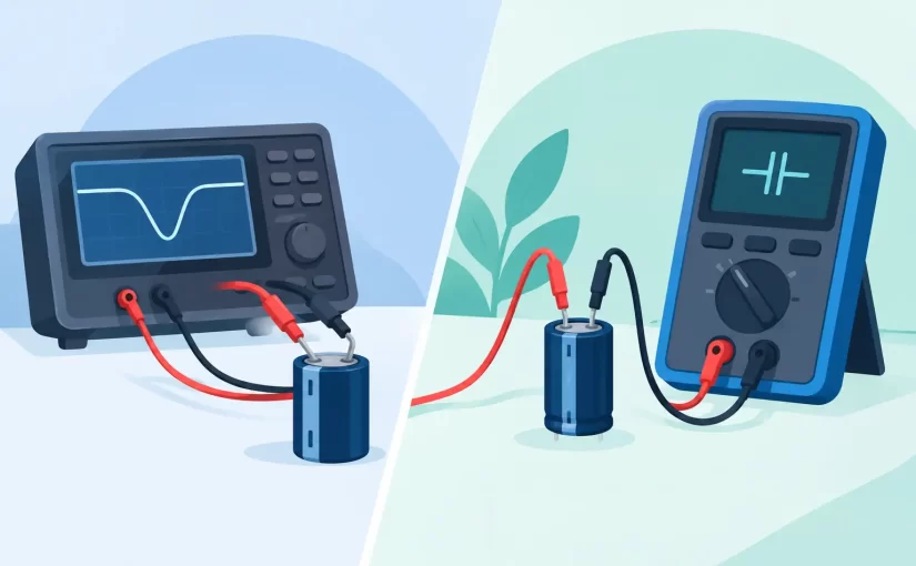
A capacitor can measure close to its printed value and still be the source of unstable rails, excessive ripple, reset faults, or intermittent startup. That is the practical distinction behind ESR testing versus capacitance testing: one test checks nominal charge storage, while the other examines resistive loss that can make a capacitor fail under operating conditions.
For PCB repair, production inspection, and design verification, neither measurement replaces the other. The useful question is not which test is better. It is which electrical behavior must be verified at the point of failure.
ESR Testing Versus Capacitance Testing: What Each Measures
Capacitance is the component’s ability to store charge. It is expressed in farads, most commonly microfarads (uF), nanofarads (nF), or picofarads (pF). A capacitance meter applies a controlled test signal, measures the response, and calculates capacitance from the relationship between current, voltage, frequency, and phase.
Equivalent Series Resistance, or ESR, is the effective resistance in series with an actual capacitor. It represents losses from electrolyte, foil, leads, terminations, dielectric behavior, and internal construction. In an ideal capacitor, ESR would be zero. In real components, it is frequency- and temperature-dependent.
A simplified capacitor model includes an ideal capacitance in series with ESR and equivalent series inductance. At low frequency, capacitance usually dominates the measurement. At higher frequency, ESR becomes increasingly significant, particularly in power-supply filtering, switching converters, and high-current decoupling applications.
This is why a 470 uF electrolytic capacitor may pass a capacitance check at room temperature but produce unacceptable ripple in a switching supply. Its capacitance may remain within tolerance while ESR has risen enough to generate heat and reduce filtering effectiveness.
Why Capacitance Alone Can Miss a Fault
Capacitance testing is highly useful for identifying open capacitors, severely degraded electrolytics, incorrect component placement, and tolerance issues. It is also essential when verifying small ceramic, film, and timing capacitors where the nominal value directly affects circuit operation.
However, a capacitance reading by itself does not establish low-loss performance. Aging aluminum electrolytic capacitors often lose electrolyte and develop higher internal resistance before their measured capacitance falls clearly outside specification. In some cases, a low-frequency capacitance measurement remains surprisingly normal.
Consider a capacitor on a DC-DC converter output. The circuit may require low impedance at the converter’s switching frequency and across its harmonic range. A capacitor with high ESR converts ripple current into voltage ripple according to the relationship V = I x ESR. As ESR rises, the same ripple current produces a larger unwanted voltage variation.
A capacitance meter will not necessarily identify that problem. It answers, “How much capacitance is present under this test condition?” It does not fully answer, “How much AC loss will this capacitor create in service?”
Capacitance tests can also be distorted by parallel components when performed in circuit. Nearby capacitors add to the measured value, while semiconductors, IC input structures, and leakage paths can affect the instrument’s calculation. For critical measurements, isolating one capacitor lead remains the most reliable method.
What ESR Testing Reveals on a PCB
ESR testing is particularly effective for diagnosing electrolytic capacitors used in power supplies, motor drives, audio equipment, industrial controls, and aging consumer electronics. An ESR meter applies an AC test signal and determines the resistive portion of the capacitor’s impedance, commonly at a frequency relevant to practical circuit behavior.
Low ESR is not universally better. The correct value depends on capacitor technology, capacitance, voltage rating, physical size, temperature rating, and intended application. A large general-purpose electrolytic naturally has a different acceptable ESR range than a low-ESR polymer capacitor or a multilayer ceramic capacitor.
The most meaningful result is therefore a comparison with the component datasheet, a known-good board, or established service limits for that capacitor family. A reading that appears low in absolute terms can still be excessive for a high-ripple switching regulator position.
ESR instruments are often useful for in-circuit screening because the applied test voltage can be low enough to avoid forward-biasing many semiconductor junctions. That does not make every in-circuit result definitive. Parallel capacitors lower the apparent ESR, PCB copper adds small resistance, and an active circuit may create misleading conditions unless power is removed and stored charge is discharged.
For a quick fault-isolation pass, in-circuit ESR measurement can be faster than lifting leads from every suspect capacitor. For acceptance testing or root-cause analysis, confirm questionable readings with the capacitor isolated from the circuit.
Test Frequency Changes the Meaning of the Reading
A measurement is only as useful as its test conditions. Capacitance and ESR are not fixed values across all frequencies. Dielectric properties, internal losses, lead inductance, and parasitic effects alter the apparent result as frequency changes.
Many handheld capacitance functions operate at relatively low test frequencies, which is appropriate for general component identification and value verification. LCR measurement at selectable frequencies provides more diagnostic information because it can show how a component behaves nearer its operating range.
For example, a capacitor used in a 100 kHz switching supply should not be evaluated only by a measurement taken far below that frequency. A higher-frequency LCR or ESR measurement may expose losses not visible in a basic capacitance mode. Conversely, measuring a large electrolytic only at high frequency may not provide the same useful capacitance result as a lower-frequency test.
Professional instruments should clearly state test frequency, test level, basic accuracy, and measurement method. A 0.1% basic-accuracy specification has value only when the operator also understands the frequency, range, fixture compensation, and component condition behind the displayed number.
Selecting the Right Test for the Job
Use capacitance testing when the nominal value is central to circuit function. This includes timing networks, resonant circuits, sensor interfaces, component sorting, and verification of small SMD capacitors before assembly. It is also the first measurement when checking for an open component or an obvious value mismatch.
Use ESR testing when a capacitor must carry ripple current or maintain low impedance in a power path. This includes input and output capacitors around regulators, bulk storage capacitors, motherboard filtering, audio supply rails, and power-conditioning sections. ESR is often the faster diagnostic measurement when symptoms point to ripple, instability, heat, or load-dependent faults.
Use both tests when evaluating an unknown or suspect electrolytic capacitor. A low capacitance reading and high ESR strongly support replacement. Normal capacitance with high ESR can also justify replacement in the correct circuit context. Low ESR with reduced capacitance may indicate a different failure mechanism, incorrect part selection, or a measurement setup issue.
For ceramic capacitors, capacitance often provides more direct value, while ESR is typically very low and may approach the practical resolution limits of portable instruments. In-circuit ceramic capacitor testing can be especially difficult because decoupling capacitors are commonly connected in parallel across supply rails.
Measurement Practice Determines Repeatability
Before testing a capacitor on a board, remove power, verify that the circuit is de-energized, and discharge high-energy capacitors safely. A charged capacitor can damage an instrument and create a shock hazard. Do not assume a board is safe simply because the power supply has been disconnected.
Clean probe contacts matter. Oxidized terminals, solder flux residue, and unstable probe pressure introduce contact resistance that can be significant when measuring low ESR. For small surface-mount components, tweezer-style probes reduce lead length, improve placement control, and help prevent accidental contact with adjacent pads.
Open- and short-compensation procedures are equally important when using LCR instruments. Compensation removes much of the fixture and probe contribution from the measurement, improving repeatability when working with low-value capacitors or low-resistance ESR readings.
Instruments such as Siborg Smart Tweezers and LCR-Reader models are designed for direct SMD contact, where probe geometry and fast component identification can materially improve PCB troubleshooting workflow. The instrument selection should still match the required frequency range, accuracy, parameter coverage, and documentation requirements of the application.
Read the Failure in Context
A capacitor is not defective because one number looks unfamiliar. The reading must be interpreted against the component type, circuit location, temperature, test frequency, and manufacturer specification. An electrolytic near a hot transformer may have a different aging profile than the same part used in a lightly loaded control circuit.
When a board fault points to power integrity, begin with ESR and compare suspect locations against known-good positions where possible. When timing, filtering value, or component identity is uncertain, start with capacitance. The most efficient technicians treat ESR and capacitance as complementary measurements, then let the circuit’s function determine which result carries more diagnostic weight.
A displayed value is only the start of the decision. The useful measurement is the one that explains what the component is doing in the circuit.