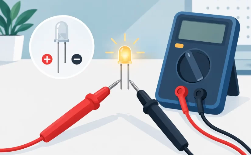
A reversed LED can turn a straightforward board repair into a misleading fault hunt. Knowing how to validate LED polarity before applying full operating power protects the device, prevents incorrect conclusions about the driver circuit, and saves time when working with small SMD packages whose markings are easy to misread.
An LED is a diode. Current must flow from the anode to the cathode for normal light output. While many indicator LEDs tolerate a modest reverse voltage, others do not, and an LED connected directly to a higher-voltage rail without proper reverse protection can fail quickly. The practical objective is not merely to identify a mark on the package. It is to confirm that the component orientation, PCB footprint, and circuit behavior all agree.
Start With the LED Package and PCB Markings
For through-hole LEDs, the longest lead is normally the anode and the shorter lead is normally the cathode. A flat edge on the lens body usually identifies the cathode. These conventions are useful during assembly, but they are not sufficient evidence on a salvaged part, a trimmed lead, or a board that has already been repaired.
SMD LEDs require closer inspection. The cathode may be marked by a line, dot, notch, chamfered corner, or a colored region on the package. The position and meaning of these marks are package-specific. A stripe on one manufacturer’s LED may indicate the cathode, while a similar visual feature on another package may be related to the internal reflector or lens structure. If the part number is available, its datasheet drawing is the primary reference.
Then inspect the PCB. Common cathode indicators include a bar on the diode symbol, a square pad, a silk-screen line, or a polarity mark adjacent to the footprint. Board markings can also be wrong, obscured, or copied from an earlier revision. Treat them as evidence to verify, especially in repair work or low-volume assemblies.
A useful circuit-level clue is the connection to the LED driver. In a typical low-side switched indicator circuit, the anode connects through a current-limiting resistor to the positive supply and the cathode connects to a transistor, IC output, or ground. In a high-side switched circuit, the arrangement is reversed at the driver, but the LED itself still follows anode-to-cathode current flow. Trace the net rather than relying only on the board legend.
How to Validate LED Polarity With Diode Mode
A digital multimeter in diode-test mode is the most direct field method for a single LED. Disconnect power from the circuit first. Verify that bulk capacitors are discharged, particularly on boards with high-voltage LED strings, switching power supplies, or mains-derived supplies.
Place the red probe on the suspected anode and the black probe on the suspected cathode. A correctly oriented LED will usually show a forward voltage reading. Red, yellow, and many green LEDs commonly read in the approximate 1.6 V to 2.4 V range. Blue, white, ultraviolet, and some high-brightness green LEDs commonly require about 2.6 V to 3.6 V or more. Some meters supply enough test voltage and current to produce a faint glow, which is a useful confirmation but should not be the only criterion.
Reverse the probes. A normal LED should indicate overload, open circuit, or a substantially different reading. The exact display depends on the meter and the surrounding circuit. The key result is directional conduction: forward bias produces a plausible LED junction voltage, while reverse bias does not.
Do not assume every diode mode is suitable for every LED. Some handheld DMMs use insufficient open-circuit voltage to forward-bias blue or white LEDs. Others limit current so tightly that a large display LED, infrared LED, or multi-junction package may not show a stable reading. An overload indication may mean reverse polarity, but it can also mean the meter cannot supply the required voltage.
Test the LED Out of Circuit When Results Are Ambiguous
In-circuit diode measurements are fast, but parallel paths can distort the result. Driver IC protection diodes, bypass capacitors, neighboring LEDs, ESD suppressors, and low-resistance traces may create an apparent forward-voltage reading in both probe directions. A meter may also energize more than one device in a series or matrix arrangement.
When the reading does not clearly establish polarity, isolate one LED terminal or remove the component. Testing the loose part eliminates most ambiguity and provides a meaningful forward-voltage measurement for comparison with identical LEDs. On compact boards, fine-pitch probes or tweezer-style contacts reduce the risk of slipping across adjacent pads and damaging a trace.
For repeated SMD inspection, a dedicated LED/component tester is often more informative than a basic diode mode. It can provide a controlled test condition and make it easier to identify whether the device conducts, emits light, or has an abnormal forward voltage. The instrument still needs to be used within its voltage and current limits. A test intended for a small indicator LED is not a substitute for a properly current-limited power source when evaluating high-power emitters.
Use a Current-Limited Supply for Functional Confirmation
A bench supply offers a second level of validation when a component is removed or when the circuit can be safely isolated. Set a conservative current limit first, then slowly raise voltage only as needed. For a standard indicator LED, a few milliamps are usually enough to confirm illumination and polarity. Do not begin at the LED’s maximum continuous current.
Connect the positive supply lead to the suspected anode and the negative lead to the suspected cathode, with a suitable series resistor if the supply is not operating in reliable current-limit mode. The LED should illuminate at its expected forward voltage. Reverse it and it should remain off. If it lights in both directions, the device may be a two-terminal bidirectional LED, a special AC LED assembly, or part of a circuit with alternate current paths.
This method is especially useful for infrared LEDs. Their emission is outside visible range, so a phone camera may reveal a faint purple or white glow that cannot be seen directly. Camera response varies, so confirm with a forward-voltage measurement rather than treating the image as definitive.
Special Cases That Defeat Simple Polarity Rules
Not every light-emitting device has one obvious anode and one obvious cathode. Bi-color LEDs may contain two inverse-parallel dies in a two-lead package, allowing different colors depending on current direction. Three-lead bi-color LEDs often have a common anode or common cathode. RGB LEDs may have common-anode, common-cathode, addressable, or multi-channel arrangements. Seven-segment displays and LED modules add further internal connections.
For these components, identify the pinout from the manufacturer documentation or map the device with a controlled low-current test. Do not use continuity mode as a substitute. Continuity thresholds and test currents vary widely by meter, and the beeper may not respond to an LED at all.
LED strings also require care. A single failed-open LED can stop an entire series string from conducting, while a failed-short LED can leave the string lit but change current sharing and thermal stress. A higher-voltage LED tester can locate faults in a string, but its output must be appropriate for the number of series junctions and the assembly under test. Never apply a string tester to circuitry that remains connected to sensitive driver electronics unless the test procedure specifically permits it.
Record the Result Before Reassembly
For repair and quality-control work, record the verified cathode orientation, forward voltage, test current or instrument mode, and whether the measurement was in circuit or out of circuit. A forward-voltage value that differs significantly from matching LEDs can indicate the wrong color bin, a damaged junction, poor contact, or a parallel circuit path.
On populated PCBs, confirm more than LED polarity before power-up: inspect the current-limiting resistor value, driver orientation, solder bridges, and the expected supply rail. Correct polarity cannot compensate for an omitted resistor or a driver configured for the wrong current.
The fastest validation sequence is visual identification, diode-mode confirmation, and a controlled functional test only when needed. That progression preserves components, produces defensible measurements, and gives the technician a clear basis for applying power with confidence.