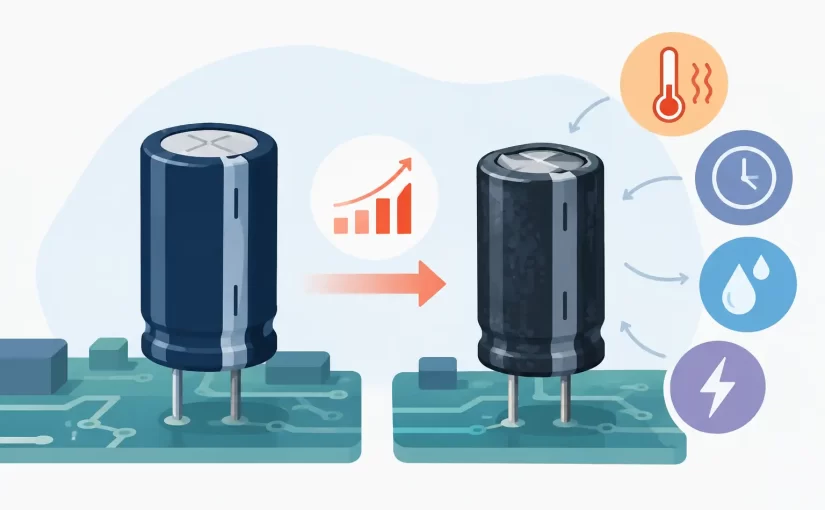
A capacitor can retain enough capacitance to look acceptable on a basic meter while its ESR has risen high enough to destabilize a switching supply, increase output ripple, or prevent reliable startup. Understanding what causes capacitor ESR increase is therefore central to practical PCB diagnosis, particularly in compact power-dense equipment where capacitors operate close to their electrical and thermal limits.
ESR, or equivalent series resistance, represents the resistive losses within a real capacitor. It includes losses in electrodes, electrolyte or dielectric material, terminals, internal connections, and lead or solder interfaces. When AC ripple current flows through that resistance, it produces heat according to I²R. As ESR increases, internal heating rises, often accelerating the same degradation that caused the increase.
What Causes Capacitor ESR Increase?
The answer depends strongly on capacitor construction. Aluminum electrolytic capacitors, conductive-polymer capacitors, tantalum capacitors, multilayer ceramic capacitors, and film capacitors do not age in the same way. For repair and quality-control work, however, four recurring causes account for most ESR changes: electrolyte degradation, excessive temperature, electrical stress, and mechanical or connection damage.
Electrolyte loss and chemical aging
In conventional aluminum electrolytic capacitors, the electrolyte is essential to low-resistance operation. Over time, electrolyte can evaporate through the seal or undergo chemical changes, especially at elevated temperature. The effective conductive path becomes poorer, which raises ESR.
This is the familiar failure mechanism in older switch-mode power supplies, monitors, industrial controls, and consumer electronics. The capacitor may show a visibly domed vent in an advanced failure state, but visual inspection is not enough. Many capacitors develop high ESR with no bulging, leakage, or other external indication.
A capacitor’s rated lifetime is commonly specified at its maximum rated temperature and rated ripple conditions. That rating is not a prediction of calendar life in every application. A 2,000-hour rating at 105°C can translate to a much longer service life at lower core temperature, but the actual result depends on ripple current, airflow, mounting location, and voltage stress.
Temperature and ripple-current heating
Heat is the most common accelerator of ESR increase in electrolytic capacitors. Ambient heat from nearby power semiconductors, transformers, resistors, or enclosed housings raises capacitor core temperature. Ripple current creates additional internal heating. The two effects combine.
A capacitor used on the output of a switching regulator may carry substantial high-frequency ripple current even when the measured DC voltage appears normal. If the capacitor’s ESR is already elevated, the I²R loss rises. This creates a feedback mechanism: higher ESR produces more heating, and more heating further degrades the capacitor.
Low-ESR capacitors are selected for many switching supply positions precisely because ripple-current capability and impedance at the operating frequency matter. Replacing such a part with a general-purpose capacitor of the same capacitance and voltage rating can shorten service life or cause poor regulator performance.
Temperature also changes the measured ESR immediately. Electrolytic capacitor ESR generally rises substantially at low temperature because electrolyte conductivity decreases. A capacitor measured in a cold field environment may read higher than it does after reaching room temperature. That is a reversible temperature effect, not necessarily permanent aging. Compare readings at a known and controlled temperature whenever possible.
Voltage stress, transients, and reverse bias
Operating near or above the rated voltage accelerates degradation. In aluminum electrolytics, sustained overvoltage can damage the oxide dielectric, increase leakage current, and generate internal heat. Repeated line transients and poorly controlled converter overshoot can create similar stress even if the nominal rail voltage is within specification.
Reverse voltage is especially damaging to polarized capacitors. Aluminum electrolytics tolerate only limited reverse bias, while tantalum capacitors can fail abruptly under inappropriate surge, reverse-voltage, or inrush conditions. ESR may rise before complete failure, but a sudden short or open failure is also possible depending on the technology and fault energy.
Ripple waveform matters as well. Capacitor heating is related to RMS ripple current, frequency-dependent impedance, and harmonic content, not simply the DC load current. A converter modification that changes switching frequency, duty cycle, or transient load behavior can increase capacitor stress without changing the nominal output voltage.
Internal construction, terminals, and solder connections
ESR is not solely a property of the capacitor’s active material. Corroded leads, cracked internal welds, weakened end seals, damaged terminations, and poor solder joints add resistance to the current path.
This is particularly relevant for surface-mount aluminum electrolytic and polymer capacitors exposed to thermal cycling, vibration, board flexure, or aggressive cleaning processes. A cracked solder joint can produce intermittent high resistance that changes when the board is pressed, heated, or vibrated. Measuring directly at the component terminations is more meaningful than probing a distant point on a power rail.
For multilayer ceramic capacitors, a mechanical crack can change capacitance, create leakage, or create an intermittent connection. ESR may not follow the same gradual aging pattern seen in wet electrolytics. The diagnostic evidence may instead be erratic impedance, board-flex sensitivity, or a short-circuit fault.
ESR Depends on Test Frequency and Conditions
An ESR value has meaning only when its measurement conditions are known. Datasheets may specify impedance, dissipation factor, ESR, or ripple-current capability at different frequencies and temperatures. A reading obtained at 100 kHz should not be compared blindly with a limit specified at 120 Hz or 1 kHz.
At lower frequencies, capacitive reactance has a larger influence on the measurement. At higher frequencies, lead inductance, internal construction, and test-fixture effects become more significant. The relevant frequency is usually tied to the circuit being diagnosed. For a switch-mode supply, high-frequency measurement is often more representative than a low-frequency capacitance-only test.
Test amplitude can also matter. Semiconductor junctions and parallel circuit paths can conduct or distort an in-circuit measurement. A meter with suitable test frequency and low test signal level helps separate component behavior from surrounding circuitry, but no in-circuit result should be treated as absolute when the topology provides a plausible alternate path.
Diagnosing Elevated ESR on a PCB
Start with the circuit function, not the capacitor label. If a supply has excessive ripple, slow startup, output oscillation, audible transformer noise, unexplained resets, or poor load regulation, examine capacitors in the input bulk, control-loop, output-filter, and auxiliary-bias positions.
Measure across the capacitor terminals with short, stable probe contact. On dense boards, tweezer-style instruments reduce lead length and make it easier to contact small SMD parts without slipping onto adjacent pads. An instrument such as a Siborg Smart Tweezers or LCR-Reader can also help verify capacitance, resistance, and inductance behavior directly at component level, depending on the model and test setup.
Interpret the ESR reading against the correct part data rather than relying only on generic pass/fail tables. Two 100 µF, 25 V capacitors can have very different acceptable ESR values because of their case size, electrolyte system, temperature rating, ripple-current rating, and intended application. A high-voltage bulk capacitor in an offline supply will not resemble a low-impedance output capacitor in a DC-DC converter.
If an in-circuit reading is questionable, compare it with a matching capacitor in an identical channel or remove one terminal for confirmation. Parallel capacitors lower the apparent ESR. Parallel semiconductor paths can produce misleading readings. Conversely, a poor solder joint or corroded pad can make the apparent ESR higher than the capacitor’s intrinsic ESR.
A useful diagnostic sequence is to inspect the waveform, measure ESR at the suspect locations, check capacitance and leakage where appropriate, then verify the surrounding stress conditions. Look for elevated ripple current, failed cooling, excessive rail voltage, startup overshoot, or a design substitution that changed capacitor type. Replacing a capacitor without correcting the stress source can turn a recurring field failure into a recurring repair.
Choosing Replacements That Will Hold Their ESR
A replacement capacitor should match capacitance and meet or exceed the original voltage rating, but those are only the starting requirements. For power applications, confirm ripple-current rating, ESR or impedance specification at the relevant frequency, temperature rating, physical size, polarity, and expected service environment.
Higher voltage rating is not automatically better if the replacement has unsuitable impedance or does not fit the board with adequate clearance. Polymer capacitors can offer low ESR and strong ripple performance, but their leakage, surge tolerance, capacitance stability, and failure behavior must still suit the circuit. In some regulator control loops, dramatically lower ESR can alter stability, so the original design requirements remain the reference.
The most useful ESR measurement is not simply a number that looks high or low. It is a measurement tied to temperature, frequency, circuit position, and the capacitor’s actual specification. That context turns a quick meter reading into a defensible repair decision and helps identify the operating condition that must be corrected before the next capacitor is installed.