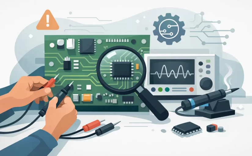
A board that is completely dead and a board that fails only after twenty minutes demand different evidence. The fastest technicians do not begin by replacing the most suspicious-looking part. They use a guide to printed circuit troubleshooting that narrows the fault from board level to circuit block, then to a component or interconnect that can be measured and verified.
The goal is not simply to find a bad component. It is to identify the failure mechanism: an open connection, a shorted rail, a leaky capacitor, a damaged semiconductor junction, a marginal solder joint, or an incorrect signal condition. That distinction prevents repeat failures and avoids introducing new defects during rework.
Start With the Failure Condition
Record what the assembly is supposed to do and exactly how it fails. Note whether the issue is constant, intermittent, temperature-dependent, load-dependent, or associated with a particular operating mode. A board that passes without load but collapses when a motor, RF stage, or display turns on often has a power-integrity issue rather than a logic fault.
Establish known-good reference conditions before probing. Confirm the correct input supply, polarity, current limit, connectors, firmware revision, and external fixtures. If a working board is available, it is one of the most useful diagnostic references. Comparing voltage, resistance, impedance, waveform shape, and component values against a known-good unit can reduce troubleshooting time substantially.
For intermittent failures, document the trigger. Flexing a PCB, applying controlled heat, cooling a localized area, or changing supply voltage can expose cracked solder joints, weak vias, and marginal components. Use these methods carefully. Thermal stress can create temporary changes that obscure the original failure if it is applied indiscriminately.
Guide to Printed Circuit Troubleshooting: Inspect First
Perform a deliberate visual inspection under adequate magnification before applying power. Look for missing parts, wrong orientation, solder bridges, lifted pads, insufficient solder fillets, damaged vias, contaminated areas, and connector wear. Darkened laminate, discolored resistors, cracked MLCCs, or residue around electrolytic capacitors may indicate the fault, but appearance alone is not proof.
Pay particular attention to component polarity and package markings. Reversed diodes, polarized capacitors, LEDs, ICs, and transistor packages are common causes of immediate malfunction after assembly or repair. On dense boards, verify pin-one orientation against the PCB designator and package datasheet rather than relying on visual assumptions.
Also inspect mechanically stressed locations: board-edge connectors, heavy inductors, large capacitors, heat-sinked devices, switches, and areas near mounting holes. Repeated vibration or connector insertion can fracture solder joints or barrel plating while leaving the exterior of the joint apparently intact.
Make Power Rails Safe and Measurable
Before energizing a suspect board, measure resistance from each supply rail to ground. A very low resistance is not automatically a fault. High-current digital rails, processor cores, and power stages can normally measure below a few ohms. What matters is whether the reading is consistent with the design, the rail topology, and a known-good board.
Use a current-limited bench supply whenever practical. Begin at the specified voltage with a conservative current limit, then observe the current draw. A supply that immediately enters current limiting indicates a short, reverse-polarity condition, failed power semiconductor, or incorrect assembly. A board drawing almost no current may have an open fuse, connector problem, disabled regulator, or broken trace.
Check the power chain in order: input protection, fuse or zero-ohm link, reverse-polarity device, switching or linear regulator, local rail filters, and load rails. Measure at both sides of series elements. A correct voltage at a regulator input does not establish that the output is stable, correctly sequenced, or capable of supplying load current.
An oscilloscope is particularly useful at switching-regulator outputs. Excessive ripple, burst cycling, repeated startup attempts, or high-frequency ringing can identify overload, bad compensation, failed feedback components, or degraded output capacitors. A DC multimeter reading can appear normal while the rail is unstable enough to reset digital circuitry.
Separate Shorts, Opens, and Leakage
A short is usually easier to locate than leakage, but both can produce similar symptoms. For a suspected shorted rail, inject a controlled low voltage with an appropriate current limit and search for localized heating. Thermal imaging is effective, but alcohol evaporation, freeze spray, or careful fingertip checks can help where appropriate. Never use a voltage that can forward-bias or damage downstream ICs.
For opens, continuity mode is useful only when interpreted correctly. Test across fuses, links, traces, vias, connector pins, and solder joints while accounting for parallel paths. A continuity beep does not guarantee a low-resistance, reliable connection under operating current. Milliohm-level resistance across a stressed path may matter in high-current circuits.
Leakage faults demand more care. Contamination, moisture, damaged protection devices, and leaky semiconductors can pull a high-impedance node away from its intended voltage without appearing as a hard short. Compare resistance readings in both polarities, inspect the area for flux residue, and measure the node during operation. Cleaning may be corrective, but it should not replace finding the contamination source.
Test Components in Circuit With Context
In-circuit measurement is fast, but parallel components affect the result. A resistor in parallel with another path reads lower than its marked value. A capacitor on a supply rail may be measured alongside dozens of other capacitors. An inductor can be shunted by semiconductor paths. Use the schematic, board layout, and surrounding topology to decide whether an in-circuit result is conclusive.
For small SMD components, tweezer-style LCR measurement provides direct access without chasing test leads across adjacent pads. Measure resistance, capacitance, inductance, and impedance as appropriate to the circuit. Test frequency matters: a value measured at a low frequency may not reveal behavior relevant to a switching converter, RF filter, or high-speed control loop.
ESR testing is valuable for capacitors in power and analog sections. A capacitor can retain a plausible capacitance value while its ESR has risen enough to produce ripple, instability, startup failure, or poor transient response. Compare capacitors of the same type and location when a known-good board is available. Do not condemn every capacitor with a nonideal in-circuit reading, especially when it is paralleled by other parts.
Diode mode is effective for checking protection diodes, rectifiers, LEDs, transistor junctions, and many IC input structures. Compare forward voltage and reverse behavior between equivalent channels or a reference board. A zero reading in both directions may indicate a short, while an open reading in both directions may be normal for the circuit or may indicate a broken connection. Circuit context decides the result.
Siborg Smart Tweezers and LCR-Reader instruments are designed for this work because the probes contact small components directly while displaying key parameters quickly. Higher-frequency LCR testing, up to 250 kHz on applicable instruments, is useful when component behavior at operating-relevant frequencies matters more than a nominal low-frequency value.
Follow the Signal Path, Not Random Test Points
Once power is confirmed, divide the circuit into functional blocks: input conditioning, reference generation, controller, driver, output stage, communications interface, or sensor front end. Identify where the expected signal enters and exits each block. This creates a sequence of meaningful measurements instead of an unstructured search.
Use a scope for timing, clock presence, reset behavior, PWM activity, data traffic, and analog signal integrity. Check amplitude, offset, frequency, duty cycle, rise time, and noise against the design expectation. A clock may be present but too low in amplitude. A reset line may release briefly and then assert because a supply rail dips. These faults are missed when only static voltage is measured.
Analog Signature Analysis can help compare a suspect node or component with a known-good signature while the board is unpowered. It is useful for identifying altered semiconductor junctions, opens, shorts, and unexpected parallel paths. Like any comparative technique, it is strongest when equivalent nodes can be tested under the same conditions.
Verify the Repair Under Real Conditions
After replacing a part or correcting an interconnect, repeat the original failure test. Confirm that the board reaches normal current draw, all regulated rails remain stable, and the intended function operates through its full duty cycle. A repair that passes at room temperature on the bench may still fail under load, vibration, or thermal stress.
Inspect the rework area under magnification. Confirm pad integrity, solder wetting, component orientation, clearance to adjacent pads, and removal of conductive debris. For production or regulated work, record the failed condition, measurements, corrective action, replacement component identification, and final verification result.
The most useful measurement is the one that eliminates a branch of the fault tree. Work from the board’s known conditions toward its unknowns, preserve evidence before rework, and let the circuit topology determine the next probe point.