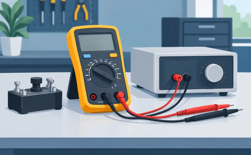
A handheld multimeter that reads 4.98 V when the circuit is known to be 5.00 V is not necessarily defective. But if that error exceeds the meter’s stated accuracy, shifts between ranges, or appears after an overload event, the instrument needs attention. Knowing how to calibrate handheld multimeters means separating a quick performance verification from an actual adjustment, then documenting results that can support engineering, production, or service decisions.
For most professional handheld meters, calibration is not a matter of turning an internal trimmer until the display looks right. Modern meters commonly use protected calibration modes, stored coefficients, reference sources, and manufacturer-specific procedures. The right process depends on the required uncertainty, the functions being verified, and whether the meter must maintain traceable calibration status.
Calibration, Verification, and Adjustment Are Different Tasks
A calibration compares meter readings against known standards and records the error at specified test points. It does not automatically include an adjustment. Verification is a narrower check that confirms whether readings remain within an acceptance limit. Adjustment changes the meter’s internal calibration constants or circuitry to reduce error.
This distinction matters in a repair department or quality system. A meter can pass calibration even when it does not display the exact nominal value of every applied standard. Its reading only needs to fall within the applicable specification and measurement uncertainty. Conversely, changing calibration data without first documenting the as-found condition removes useful evidence about drift, damage, or misuse.
For a meter used to troubleshoot low-voltage electronics, a basic voltage and resistance verification may be sufficient between formal calibration intervals. For production acceptance testing, safety-critical field work, or measurements used in compliance records, use a documented calibration procedure and traceable standards. A NIST-traceable certificate establishes the reference chain, but it does not by itself guarantee that a particular measurement setup is free of lead, contact, temperature, or operator error.
What You Need to Calibrate a Handheld Multimeter
The reference equipment must be more accurate than the device under test by a meaningful margin. A common target is a test uncertainty ratio of 4:1 or better, although the appropriate ratio depends on the quality system and the meter specification. Calibrating a 0.1% handheld meter with a reference that is only 0.2% accurate does not produce a defensible result.
At minimum, prepare a stable voltage reference or multifunction calibrator, precision resistance standards, quality low-thermal test leads, suitable adapters, and a record sheet or calibration software. AC voltage and current functions require standards that specify frequency, waveform quality, burden capability, and uncertainty. Capacitance, frequency, continuity, diode test, and temperature functions each require dedicated sources or simulators if they are included in the calibration scope.
Use standards with current calibration certificates and allow both the standards and meter to stabilize in the same environment. Most specifications are stated near 23 C, often with a limited temperature range and humidity condition. A meter brought in from a cold service vehicle can show temporary offset or gain changes. Allow at least 30 minutes of warm-up unless the manufacturer specifies otherwise.
Before connecting anything, inspect the meter. Check the case, rotary switch, input jacks, fuse ratings, battery condition, display, probe insulation, and lead resistance. Replace damaged leads rather than attempting to compensate for them in the results. For current ranges, confirm that the correct high-energy fuse is installed and that the input jack labeling is readable.
How to Calibrate Handheld Multimeters Step by Step
Start with the manufacturer’s service manual or calibration procedure. It defines required standards, test points, settling times, allowable errors, and whether adjustment is permitted. A user manual rarely contains enough information for a full calibration.
Establish the As-Found Condition
Record the meter model, serial number, firmware revision if available, environmental conditions, accessories used, and the date. Set the meter to its default configuration. Disable relative mode, peak capture, filtering, Bluetooth logging, and other functions that can affect the displayed value.
Apply each specified reference point and allow the reading to settle. Record the applied value, the displayed value, the calculated error, the allowable tolerance, and a pass or fail result. Cover the ranges that matter to the intended work, not just a convenient midscale DC voltage point.
For DC voltage, test zero or near zero, a low-range point, midrange, and a high-range point. For resistance, use standards that exercise the low-ohm range as well as higher ranges. Short the leads first to identify their contribution. On a 2-wire handheld meter, lead and contact resistance can dominate low-resistance measurements unless the meter has a relative function or the procedure accounts for the offset.
Verify DC Voltage and Resistance Carefully
Connect the voltage standard directly to the voltage input and common terminal. Select the required range manually when the procedure calls for it. Autoranging can be useful in normal troubleshooting, but fixed-range tests better identify range-specific errors.
Readings should be evaluated against the meter specification in the form commonly used by manufacturers: a percentage of reading plus counts. For example, an accuracy of ±(0.5% of reading + 2 counts) has two components. At 10.000 V on a meter with 1 mV resolution, the percentage component is 50 mV and the counts component is 2 mV, for a total allowable error of 52 mV. The exact calculation must use the selected range resolution, not an assumed display resolution.
For resistance, use clean connectors and avoid touching exposed terminals with your fingers. Body resistance and surface contamination can affect higher resistance values. If testing megohm ranges, use guarded fixtures or the manufacturer-recommended setup when available, and allow additional settling time.
Add AC, Current, and Specialized Functions Only When Supported
AC calibration is more demanding than DC calibration. Meter bandwidth, crest factor, true-RMS conversion, and signal amplitude all influence the result. Test the specified frequencies and amplitudes rather than assuming that a 60 Hz sine wave proves performance at 1 kHz or 10 kHz. A non-true-RMS meter may read accurately only for sine waves within its defined range.
Current ranges require particular care. A current calibrator or a suitable source with a precision shunt is preferable to improvised bench setups. Never move a lead from the voltage jack to the current jack while the source is energized. Verify the meter fuse before testing, and ensure the source can tolerate a momentary open circuit if the fuse operates.
Frequency, duty cycle, capacitance, diode, continuity, and temperature functions should be checked only with appropriate standards. A simple voltage reference cannot validate capacitance accuracy or diode-test current. For component-level diagnostics, a handheld multimeter also cannot replace an LCR meter or ESR meter where test frequency, AC stimulus, and equivalent-series-resistance resolution determine the result.
Compare Results and Decide Whether Adjustment Is Needed
If all results are within limits, retain the as-found data as the as-left data, apply the calibration status label if required, and set the next due date according to actual use and quality requirements. A yearly interval is common, but it is not universal. High-use field meters, instruments exposed to temperature cycling, and meters used for tighter tolerances may need more frequent verification.
If the meter fails, do not immediately adjust it. Check the battery, leads, input protection, range selection, reference setup, and environmental conditions. Repeat the failed point with a second standard if practical. A consistent failure may indicate genuine drift; an intermittent result may point to contaminated jacks, damaged leads, a weak battery, or switch-contact problems.
Adjustment should be performed only with the approved procedure, correct access method, and required standards. Many professional instruments store calibration constants in nonvolatile memory and may require a password, service software, or a controlled sequence. Unauthorized adjustment can invalidate prior records, compromise safety ratings, or make future traceability difficult.
Documentation Makes Calibration Useful
A useful calibration record identifies the standards used, their certificate numbers and due dates, the environmental conditions, test points, tolerances, actual readings, uncertainty statement where applicable, technician identity, and final status. Include repair actions and the post-adjustment results when adjustment was necessary.
For a lab managing several handheld instruments, trend the error over time. A meter that passes every year but drifts steadily toward one tolerance limit may warrant a shorter interval or preventative service. This is more informative than treating every calibration event as an isolated pass or fail.
Siborg Systems instruments are supplied for precision electronic measurement workflows, and calibration documentation should match the level of confidence required by the work. A quick bench check can protect a troubleshooting session; traceable calibration supports decisions that must stand up to audit, production review, or customer requirements.
When the reading affects a component decision, a repair release, or a safety measurement, treat calibration as measurement control rather than paperwork. The best result is not a display forced to match a nominal number, but a handheld meter with known error, verified performance, and records that make its measurements credible.