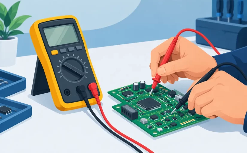
A board can show the correct supply voltage and still fail because of one cracked MLCC, an open resistor, or a semiconductor junction that behaves incorrectly under test. Handheld multimeters are the first instrument many technicians reach for in that situation, and for good reason: they establish whether power, ground, continuity, resistance, and basic junction behavior are present before more specialized measurements begin.
For PCB work, however, a handheld meter is only as useful as its accuracy, input protection, probe access, update behavior, and the measurement functions that match the fault. A general-purpose digital multimeter can quickly confirm a 12 V rail or locate a broken trace. It cannot always identify the value or condition of a small component in circuit, particularly when parallel paths influence the reading. Selecting the right instrument starts with recognizing that boundary.
What Handheld Multimeters Do Best
A professional handheld multimeter is the primary tool for electrical verification. In field service, production troubleshooting, and bench repair, it is used to establish basic circuit conditions quickly and safely. DC and AC voltage measurement confirm supply rails, battery condition, regulator output, signal presence, and mains-related inputs. Resistance and continuity locate open conductors, damaged fuses, poor connectors, and unintended shorts.
Diode test is equally valuable when evaluating discrete diodes, bridge rectifiers, transistor junctions, and protection devices. The displayed forward voltage can reveal a shorted junction, an open device, or a result that differs substantially from a known-good circuit. Current measurement can expose excessive load, but it requires more planning than voltage measurement because the meter must be placed in series and configured for the expected current range.
For these tasks, speed matters. A meter that settles quickly, presents readable values, and has a practical continuity response reduces the time spent moving between test points. Basic accuracy matters as well. When determining whether a 3.30 V rail is within tolerance, a low-cost meter with broad error limits may be adequate. When verifying a precision reference, low-resistance connection, or calibrated production fixture, the accuracy specification and calibration status deserve closer attention.
Specify the Meter Around the Work
The best handheld multimeter is not simply the model with the longest function list. It is the one whose electrical ratings and operating details fit the circuits being tested.
Accuracy, resolution, and range
Basic DC voltage accuracy is often the first specification to compare. It is commonly expressed as a percentage of reading plus a number of counts. Both terms affect the result. A meter specified at 0.1% of reading plus two counts will generally provide more confidence on low-voltage electronics than one specified at 1% plus several counts, assuming both are used within their stated conditions.
Resolution should be evaluated with the range. A display with more digits is not automatically more accurate, but sufficient resolution prevents small changes from being hidden by coarse range steps. For example, monitoring millivolt-level variation across a current-sense resistor calls for a range and resolution appropriate to that signal. Measuring a 120 V branch circuit does not require the same resolution, but it does require suitable safety ratings and leads.
Input protection and safety category
A multimeter used near mains power must be selected for the installation category and voltage level of the environment. CAT ratings are not marketing labels. They describe the meter’s ability to withstand transient energy associated with different parts of an electrical installation. A meter appropriate for low-energy electronics work may not be appropriate for panel, feeder, or service-entrance measurements.
The leads, probes, fuses, and accessories must match the meter’s ratings. Damaged insulation, exposed metal beyond the probe tip, incorrect current jacks, and replacement fuses with unsuitable interrupt ratings all compromise the protection system. In PCB service, where low-voltage work is common, technicians can still encounter charged primary-side capacitors, power-factor-correction stages, and off-line power supplies. Treat those areas as high-energy circuits until they are verified safe.
Functions that affect diagnostic speed
Continuity response, diode-test voltage, capacitance range, frequency measurement, min/max capture, and relative mode can each affect workflow. A responsive audible continuity function is more productive when tracing connectors or checking vias than a meter that pauses before sounding. Relative mode helps remove lead resistance when making low-ohm comparisons. Min/max capture can record an intermittent supply sag that a normal display update misses.
True-RMS AC measurement becomes relevant when the waveform is not a clean sine wave. Variable-speed drives, switching power supplies, dimmers, and distorted line conditions can produce misleading readings on an average-responding meter. That does not mean every PCB bench requires True RMS, but it is a practical requirement for many field and industrial applications.
Where a Multimeter Reaches Its Limit
Resistance and continuity readings on a populated board must be interpreted in context. The meter applies a test stimulus, then measures the response of the complete network connected to the probes. A nominal 10 kΩ resistor may read lower because it is paralleled by another path. A capacitor may cause a changing resistance indication as it charges. Semiconductor junctions, IC input structures, and energized circuits can create results that are not meaningful or safe to interpret as ordinary resistance.
Capacitance functions are useful for loose components and selected out-of-circuit checks, but they are not a full substitute for impedance measurement. They may not reveal equivalent series resistance, test a part at a relevant frequency, or distinguish a capacitor’s behavior from the surrounding circuit. Similarly, inductance is not a standard function on many handheld multimeters, and a resistance measurement cannot verify inductance value or quality factor.
This is where a dedicated LCR or ESR instrument becomes more efficient. On dense boards, tweezer-style probes can contact small SMD terminations directly without juggling two conventional probes. A component tester operating at appropriate frequencies can measure resistance, capacitance, inductance, and ESR with information that a multimeter cannot provide. Instruments such as Siborg’s Smart Tweezers and LCR-Reader families are intended for this component-level work, including in-circuit screening where circuit conditions permit a valid measurement.
The distinction is practical rather than competitive. Use a multimeter to verify the circuit’s electrical state. Use an LCR or ESR meter when the question is whether a component has the correct value or loss characteristic. Use an oscilloscope when timing, ripple, transients, or waveform shape is the fault mechanism. Experienced troubleshooting moves among these tools instead of forcing one tool to answer every question.
Probing Practices That Preserve the Measurement
Probe contact is often the limiting factor on modern assemblies. Standard 4 mm probe tips are reliable for terminals and test points but can bridge adjacent pads on fine-pitch boards. Fine insulated probe tips, hook clips, spring probes, and dedicated SMD tweezer probes improve access while reducing the chance of accidental shorts.
Before measuring resistance, diode drop, capacitance, or an in-circuit component, remove power and discharge stored energy. Confirm the absence of voltage with the multimeter before connecting a sensitive LCR or ESR instrument. For comparative troubleshooting, measure the same point on a known-good board when possible. A single number rarely proves a fault; a meaningful difference between identical circuits often does.
Ground reference selection also deserves attention. A reading taken between a regulator output and a remote ground may include voltage drop across a return path. Measure close to the relevant component when checking local rails. For low-resistance work, compensate for lead resistance with relative mode if the meter supports it, or use a four-wire method when the required accuracy justifies it.
Calibration and Documentation in Professional Workflows
For repair work, a meter may only need to distinguish normal from abnormal. In quality control, production test, engineering verification, and regulated maintenance, documented measurement confidence has greater value. A current calibration record and a NIST-traceable calibration certificate support internal quality procedures and help establish the reliability of recorded test results.
Calibration does not eliminate the need for good technique. Temperature, battery condition, lead condition, source impedance, test frequency, and range selection can all influence a result. The meter’s published specifications also apply only under stated conditions. A disciplined workflow records the instrument used, the range and function, the test location, and the relevant operating condition when the measurement will be used for a formal decision.
A Practical Instrument Set for Board Service
For most electronics teams, the efficient baseline is a quality handheld multimeter paired with a component-level measurement tool. The multimeter handles voltage, continuity, resistance, diode checks, and basic current verification. The LCR or ESR instrument addresses uncertain passive components, especially small SMD parts where removing a component simply to identify it wastes time and risks board damage.
Add an oscilloscope when the fault depends on switching behavior, communication timing, ripple, startup sequence, or intermittent transients. Bluetooth-enabled instruments can also improve documentation and repeatability when readings must be captured on a mobile device or PC rather than copied manually from a display.
A handheld meter earns its place by answering the first electrical questions quickly and reliably. Choose one with the accuracy, safety category, input protection, functions, and probe system your work actually requires, then pair it with specialized measurement tools when the diagnosis moves from circuit state to component behavior.