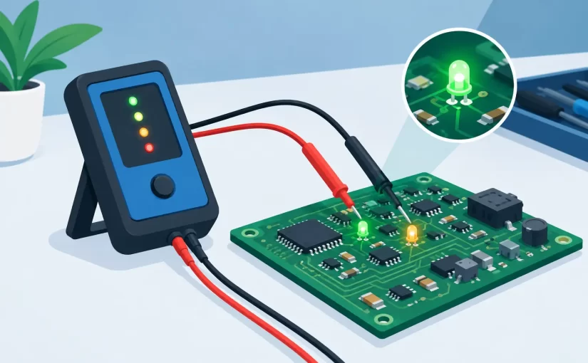
A dim display, an intermittent status indicator, or a dark LED backlight strip can turn a straightforward repair into an extended fault-isolation job. LED testers reduce that uncertainty by applying a controlled test stimulus directly to the device or LED string, revealing polarity, illumination, and approximate forward voltage without requiring a powered circuit.
For PCB repair, production inspection, and field service, the useful question is not simply whether an LED lights. The instrument must apply an appropriate voltage and current, provide a meaningful reading, and let the operator reach the component without damaging fine pads, neighboring parts, or the LED itself.
What LED Testers Actually Measure
At the component level, an LED is a diode with a light-emitting junction. A tester forward-biases that junction. When the applied voltage exceeds the LED’s forward-voltage requirement and current is limited to a safe value, the device emits light. Reversing the connection should normally produce no illumination.
A basic LED test therefore establishes three practical facts: whether the device conducts in the expected direction, whether it emits light, and the approximate forward voltage at the applied current. These results are often enough to identify an open LED, reversed installation, damaged bond wire, or incorrect replacement part.
Forward voltage is not a fixed identification number. It varies with LED chemistry, current, junction temperature, binning, and optical color. A red indicator LED may conduct at a substantially lower voltage than a white or blue LED, while infrared emitters can function normally without visible light. Treat the displayed voltage as a diagnostic measurement, not as a complete part specification.
A multimeter diode mode can test many discrete LEDs, but it may not supply enough voltage to illuminate white, blue, ultraviolet, or series-connected LEDs. Dedicated instruments may provide a higher test-voltage range for these applications. That capability is valuable, but it also demands controlled current and disciplined probing.
Why Test Current and Voltage Range Matter
LEDs are current-driven devices. Once forward-biased, a small voltage change can create a significant change in current. A useful tester limits current rather than leaving the operator to infer safe conditions from an open-circuit voltage rating.
Low-current test modes are generally preferred for small indicator LEDs, SMD LEDs, and LEDs tested in sensitive assemblies. They can confirm conduction and polarity while reducing stress on the junction. A higher-voltage mode is necessary when checking multiple LEDs in series, such as display backlight strips, but the tester should still regulate current to prevent excessive dissipation.
Higher range is not automatically better. Applying a high-voltage LED test to a single small SMD LED can create unnecessary stress if the instrument’s current limit is unsuitable. Conversely, a low-range diode test can falsely suggest that a healthy white LED or a multi-LED string is open because the meter cannot reach its required forward voltage.
The correct mode depends on the device under test. Use low current and direct probes for individual board-mounted LEDs. Use a controlled higher-voltage range for strings only after confirming the string topology and disconnecting or isolating circuitry when required.
Reading a Dim or Uneven Result
An LED that lights dimly is not necessarily defective. Test current may be deliberately low, and some packages distribute light in a way that is difficult to see from a particular angle. Compare like components using the same test mode and viewing conditions.
Uneven brightness across a string can be more informative. A noticeably dim device, a device that requires a different voltage, or one that flickers during gentle probe movement may point to junction degradation, cracked solder joints, contamination, or a damaged trace. Repeat the test to separate a repeatable electrical result from an unstable mechanical connection.
In-Circuit LED Testing Has Limits
Testing an LED on a populated PCB is fast, but the surrounding circuit can change the result. Parallel diodes, driver IC outputs, protection networks, capacitors, and alternate current paths may make a good LED appear shorted, open, or unusually low in forward voltage.
Start with the board unpowered unless the service procedure specifically calls for powered measurements. Disconnect batteries, external adapters, and stored-energy sources. A tester’s applied voltage can interact unpredictably with active circuitry, particularly in LED drivers and display modules.
If an in-circuit measurement is ambiguous, compare it with an identical channel or neighboring LED. Symmetry is often the most useful reference in a repeated circuit. If no comparison point exists, isolate one LED lead or remove the component for a definitive test. That extra step is slower, but it avoids replacing a functioning part because of a misleading in-circuit path.
Backlight assemblies deserve special caution. Some strips contain integrated protection elements, multiple dies, or series and parallel arrangements that do not behave like a single discrete LED. A string tester can quickly identify whether a strip conducts and illuminates, yet it may not identify every marginal LED in a complex assembly. Localized voltage comparison and visual inspection remain useful follow-up methods.
Probe Access Determines Diagnostic Speed
The electrical capability of LED testers matters only when the probes can contact the device reliably. Conventional pointed leads are practical for through-hole LEDs, exposed test pads, connector pins, and larger strips. Fine SMD LEDs often require more controlled contact.
Sharp probes can slip off small pads and bridge adjacent conductors. For fine-pitch PCB work, insulated needle probes, spring probes, or tweezer-style accessories give better positional control. The goal is firm contact with minimal force. Pressing hard enough to flex a board can temporarily restore a cracked joint and conceal the fault being investigated.
Probe placement also affects the reading. Contact the actual LED terminals or known points in the same electrical path. Testing across a resistor, driver transistor, or connector section may show a voltage response without proving that the LED junction is intact. Board layouts, polarity marks, and circuit documentation should guide the measurement whenever available.
For production or recurring repair work, a repeatable fixture can be more valuable than faster handheld probing. A fixture establishes consistent contact pressure, orientation, and test conditions, improving pass-fail decisions across batches. Handheld tools remain the better choice for rework, field diagnostics, and varied board geometries.
Selecting LED Testers for the Workbench
Choose an instrument based on the LED types and failure modes encountered most often. A technician repairing consumer displays needs controlled higher-voltage testing for strips and modules. A PCB rework specialist may place greater value on low-current component testing, fine probes, and a compact form factor. Manufacturing teams may prioritize repeatable test conditions and documented inspection procedures.
Evaluate the instrument’s maximum test voltage, current-limit behavior, polarity indication, display readability, and supported LED configurations. Confirm whether the tester is intended for individual LEDs, series strings, or both. A visible-light result alone is insufficient when servicing infrared, ultraviolet, or enclosed optical devices, where current and voltage readings carry more diagnostic weight.
It is also useful to separate LED verification from broader component analysis. A dedicated LED function establishes junction behavior quickly. An LCR meter, ESR meter, or digital multimeter addresses the resistors, capacitors, inductors, supply rails, and driver components that may be responsible when a known-good LED does not operate in the circuit.
Siborg’s component-testing approach is built around direct access to small devices on boards, where probe control and repeatable measurements can save more time than a general-purpose test setup. For LED diagnostics, that same discipline applies: test the junction first, then follow the circuit path when the result does not match the observed failure.
A Practical Test Sequence
Begin by inspecting the LED and surrounding area under magnification. Look for discoloration, cracked lenses, lifted pads, corrosion, missing components, and thermal damage. Then verify the board is unpowered and select the lowest appropriate test mode.
Connect the probes with attention to polarity and observe both illumination and the electrical reading. Reverse the probes to confirm expected blocking behavior. If the LED is in circuit, compare it to a matching device or channel before declaring it defective.
When testing a series string, begin with the controlled string-capable mode and watch for partial illumination, flicker, or an unexpected voltage requirement. If the result is unclear, divide the string into smaller sections rather than increasing test stress. This approach narrows the fault while protecting uncertain components.
A reliable LED test is a measured decision, not a brightness check. Use controlled current, select a voltage range that matches the assembly, and treat every in-circuit result in the context of the surrounding design. That discipline turns a small handheld tester into a practical tool for finding faults before they become unnecessary board replacements.