A diode that reads 0.62 V in diode mode may be perfectly healthy, while a 0.28 V reading may also be correct. The difference is not a meter error by default. To understand how to measure diode forward voltage, you need to account for diode type, test current, junction temperature, and whether the device is still connected to a circuit.
For troubleshooting, a digital multimeter’s diode-test function is usually the fastest first check. For characterization, LED verification, or comparison against a production specification, the test method must define current and temperature. Forward voltage is not a fixed property stamped onto the component. It is the voltage drop across a forward-biased PN junction at a particular current.
What diode forward voltage actually represents
A diode conducts when its anode is at a higher potential than its cathode. In that forward-biased condition, the junction develops a voltage drop called forward voltage, commonly written as Vf. A meter in diode mode applies a small, controlled test current and displays the resulting voltage.
That detail matters. A silicon switching diode may display approximately 0.55 to 0.80 V at a multimeter’s low test current, yet operate at a different forward voltage when carrying its rated circuit current. A rectifier diode, Schottky diode, germanium diode, and LED all have different expected ranges.
Temperature also changes the result. For a conventional silicon PN junction, forward voltage generally decreases as junction temperature rises. Comparing readings is most useful when the same meter, test current, and approximate temperature are used for each component.
How to measure diode forward voltage with a multimeter
Use a DMM with a dedicated diode-test setting rather than a resistance range. Resistance mode can indicate gross shorts or opens, but it does not provide a controlled, interpretable forward-voltage result.
Prepare the circuit and instrument
Turn off circuit power before connecting the meter. Disconnect batteries, remove external supplies, and discharge capacitors where stored energy is possible. A charged electrolytic capacitor can produce misleading readings or damage a meter input.
Set the multimeter to diode mode, normally marked with a diode symbol. Check the meter manual if the symbol shares a switch position with continuity. Some instruments require a function-button press to select diode test.
For a loose component, identify the terminals before probing. The cathode of many axial diodes is marked by a band. On SMD diodes, cathode marking may be a line, a dot, a beveled edge, or a package-specific code. Verify the package documentation when the marking is unclear, especially with small SOT and DFN devices.
Apply the probes in the forward direction
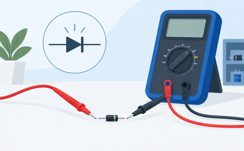
Place the red probe on the anode and the black probe on the cathode. Most modern DMMs source current from the red probe in diode mode, but confirm this behavior on an unfamiliar instrument using a known diode.
The display should settle on a voltage value. Record the value in volts. For example, a display of 0.647 means 647 mV of forward voltage at that meter’s diode-test current.
Reverse the probes next. A good diode should normally display OL, an overload indication, or a reading far outside the forward result. This reverse-direction check is essential because a forward reading alone cannot distinguish every failure mode.
Interpret the basic results
A useful first-pass interpretation is straightforward:
- A normal forward reading and OL in reverse usually indicate a functioning diode.
- A reading near 0 V in both directions suggests a shorted junction.
- OL in both directions suggests an open diode, incorrect probe contact, or a meter whose diode-test voltage cannot overcome the device’s threshold.
- Similar nonzero readings in both directions often indicate a parallel circuit path rather than a failed diode.
These are diagnostic patterns, not final component specifications. Measure against the device datasheet when acceptance limits matter.
Expected readings by diode type
Standard silicon signal and rectifier diodes commonly read about 0.55 to 0.80 V in a handheld meter’s diode mode. Higher-current rectifiers can differ from small-signal parts because of die construction and the meter’s test current.
Schottky diodes often read lower, commonly about 0.15 to 0.45 V. Their lower forward drop is a design advantage in power conversion, but it also means that a low reading is not automatically evidence of a short. Compare the result with the specified part type.
Germanium diodes may read roughly 0.20 to 0.35 V. They also have higher leakage than silicon devices, so reverse readings can require more careful interpretation.
LEDs require additional context. A red LED may measure around 1.6 to 2.1 V, while blue, white, and many ultraviolet LEDs may require 2.8 to 3.6 V or more. Many handheld meters cannot provide enough open-circuit test voltage to forward-bias higher-voltage LEDs. An OL display in diode mode can therefore mean either an open LED or an instrument limitation.
When testing LEDs, use an LED tester or a controlled current source if the meter cannot drive the device. The target is a defined current and an observed Vf, not simply obtaining any illuminated condition.
Why in-circuit diode measurements can mislead
Testing a diode on a populated PCB is efficient, but the circuit around it can create alternate paths. Resistors, IC input protection structures, transformer windings, capacitors, and other semiconductor junctions may all affect the displayed value.
A diode across a motor coil or relay coil, for example, may be influenced by the coil resistance and associated suppression circuitry. A diode inside a power supply may have parallel paths through MOSFET body diodes, controller ICs, or transformer windings. In these cases, the meter is measuring the network, not just the intended junction.
Start with an in-circuit check when access is limited and use it as a comparison tool. Compare identical channels, phases, or board sections when possible. If the result is ambiguous, lift one diode lead or remove the component for a definitive measurement. Lifting one terminal is normally sufficient to eliminate most parallel paths while reducing rework compared with full removal.
For small surface-mount parts, probe placement is often the limiting factor. Fine test tips or tweezer-style contacts reduce the chance of touching adjacent pads and provide more repeatable contact pressure. Siborg Systems instruments are designed for direct access to small PCB components where conventional probes can be slow and imprecise.
Match the measurement method to the job
A DMM diode test is appropriate for rapid fault isolation: open versus short, polarity confirmation, and rough comparison between similar devices. It is not a replacement for a datasheet-defined forward-voltage test.
For a controlled Vf measurement, use a regulated current source set to the relevant operating or inspection current. Connect the diode in series with the source, allow the reading to stabilize, and measure voltage directly across the diode terminals with a high-input-impedance voltmeter. Keep the test duration short for power devices and high-current LEDs because self-heating shifts Vf.
The datasheet condition should drive the setup. If a diode specifies Vf maximum at 1 A and 25 C, a measurement at 1 mA in a DMM tells you little about compliance at 1 A. Conversely, forcing a small signal diode to a high current simply to imitate a power-device test can destroy it.
For production or incoming inspection, document the test current, ambient temperature, fixture contact method, polarity, settling time, and pass limits. Repeatability depends as much on these controls as on meter resolution. A calibrated instrument supports traceability, but calibration cannot correct an undefined test condition.
Common measurement errors to avoid
The most frequent error is using continuity mode and assuming the beep confirms a good diode. Continuity thresholds vary by meter and may beep for a low-voltage Schottky diode, a partial short, or an unintended parallel path. Read the actual diode-mode voltage instead.
Another error is treating a typical forward voltage as an absolute pass/fail number. A 0.70 V silicon diode is not universally good, and a 0.30 V diode is not universally bad. Part family, current, temperature, and board context determine what is plausible.
Poor contact can also look like an open junction. Oxidized leads, conformal coating, damaged SMD pads, and probe slip add uncertainty. Clean the accessible contact point and hold probes steadily before calling a component defective.
A forward-voltage reading becomes valuable when it is tied to a known test condition and compared with the right reference: the datasheet, a verified-good board, or an identical component measured the same way. That discipline turns a quick meter check into evidence you can use for repair, quality control, and failure analysis.