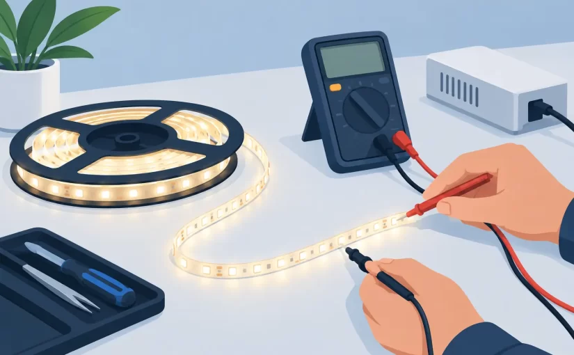
A backlight can appear completely dead when only one LED in a series string has opened. A strip can also test good on the bench yet fail in the product because its connector, current driver, or thermal path is the actual fault. Knowing how to test LED strips means separating the strip itself from the power and control circuitry, then applying enough voltage and current control to produce a meaningful result without overstressing the LEDs.
This procedure applies to common constant-current LED strips used in LCD TV backlights, signage, appliances, under-cabinet fixtures, and general lighting. Addressable RGB strips require a different approach because they contain integrated control ICs, but the same basic checks for supply voltage, continuity, and physical damage still apply.
Start with the strip type and its electrical rating
Before connecting a meter or power source, identify whether the strip is a low-voltage parallel design or a high-voltage series string. This determines what a normal reading looks like and what test equipment is appropriate.
A 12 V or 24 V flexible lighting strip normally has repeated segments. A 12 V single-color segment often contains three LEDs and one resistor, while a 24 V segment may use six LEDs or another series-parallel arrangement. These strips can usually be evaluated section by section with a multimeter diode function, provided the strip is disconnected from its controller.
LCD backlight strips are different. They commonly use many white LEDs wired in series, sometimes with several series strings in parallel. One white LED has a forward voltage near 2.7 V to 3.3 V at modest current. A 10-LED string may therefore require roughly 30 V, while a long TV strip assembly can require well over 100 V. Do not attempt to power an unknown backlight strip from an unregulated high-voltage source.
Read the markings on the PCB, label, or original power supply. Record the polarity, rated input voltage, strip part number, and connector pin count. If there are multiple channels, identify whether each pair of terminals feeds an independent string.
Inspect before applying power
Visual inspection is not a substitute for measurement, but it often determines where to measure first. Look closely at each LED package, solder joint, copper trace, connector, and resistor. A browned PCB, lifted pad, cracked lens, darkened phosphor, or blistered LED lens is strong evidence of a local thermal failure.
For flexible strips, bends near connectors and cut points deserve particular attention. Copper traces can crack beneath the solder mask, producing an intermittent open that looks normal until the strip is flexed. On rigid aluminum-core backlight strips, check for corrosion around lenses, damage from prying tools, and poor contact between the strip and its heat-spreading chassis.
If a failed LED has been replaced previously, inspect the repair for correct polarity and adequate solder wetting. An LED installed backward will block the entire series string. Excess solder can also bridge pads or interfere with lens placement.
Test individual LEDs with a multimeter
A digital multimeter diode mode is the fastest first test for accessible LEDs. Disconnect the strip from all power and control boards. Place the red probe on the LED anode and the black probe on the cathode. Many meters source enough current to make a healthy low-power LED glow faintly. A white backlight LED may show a forward-voltage reading, glow briefly, or show overload because the meter’s diode-test voltage is too low.
Reverse the probes. A healthy LED should not conduct significantly in reverse. Compare readings with neighboring LEDs of the same type rather than relying only on one absolute number.
A reading near 0 V in both directions suggests a shorted LED or a solder bridge. An overload indication in both directions can mean an open LED, incorrect probe placement, poor contact, or insufficient diode-test voltage. Check the probes against a known-good LED before condemning the device.
For SMD LEDs, conventional pointed probes can slide off tiny pads and create inconsistent results. Fine-pitch probes or tweezer-style test instruments improve repeatability by contacting both terminals directly. This is especially useful when confirming whether one component is open while it remains on a populated board. Keep in mind that parallel circuit paths can affect an in-circuit reading. When a result is ambiguous, isolate one LED terminal or test the strip out of circuit.
Use a dedicated LED tester for series strings
An LED strip tester is the practical tool for testing long backlight strings. These instruments typically provide automatically adjusted DC voltage with current limiting, allowing a technician to energize a series string without calculating and assembling a high-voltage bench setup. Connect the tester to the marked positive and negative strip terminals, beginning with the lowest available current setting.
A good string should illuminate uniformly. Watch for one LED that is dimmer, a section that does not light, or a string that requires an unusually high or low voltage compared with an identical channel. Record the operating voltage shown by the tester. Comparison is valuable: two nominally identical strips should have similar forward-voltage requirements at the same test current.
Do not use the tester result alone to judge LED health. A string may illuminate at the tester’s low current but fail under normal operating current because of thermal damage, weak bonds, or marginal solder joints. If the product fails after a brief warm-up, run the strip at a controlled current and observe it for several minutes while monitoring temperature.
Test low-voltage strips by segment and current draw
For 12 V and 24 V strips, apply the rated voltage from a current-limited bench supply. Start with a conservative current limit, then raise it only as needed for normal illumination. The expected current depends on strip density and LED type, so compare against a known-good sample, manufacturer specification, or another undamaged section of the same installation.
If the entire strip is dark and the supply immediately enters current limit, disconnect it and measure resistance across the input. Very low resistance may indicate a shorted protection diode, reversed-polarity damage, a bridged solder joint, or a failed controller rather than failed LEDs.
If only one segment is dark, measure voltage at that segment while the strip is powered. A normal supply voltage across the segment with no light points to an open LED, open resistor, or failed connection within that section. No voltage at the segment points upstream to a broken trace, connector, switch, or control channel.
For RGB and RGBW strips, test each color channel independently. The common anode or common cathode configuration matters. A controller output that is pulse-width modulated may not produce a stable reading on a basic meter, so use a scope or meter with suitable duty-cycle capability when the control signal is in question.
Separate strip failures from driver failures
A functional LED strip does not prove that the installed system is functional. The driver must deliver the correct voltage or, for backlights, the correct regulated current. Measure at the driver output only when you understand the circuit and have suitable probes, meter ratings, and safe access.
For a constant-current driver, output voltage is a consequence of the connected LED string. An open string can cause the driver to rise toward its maximum compliance voltage and then shut down or cycle. A shorted LED can reduce required output voltage and may trigger fault protection. Therefore, a fluctuating output is not automatically a bad driver.
Check the driver input first. Confirm its DC supply, enable signal, dimming input, and connector integrity. Then compare the suspect channel with a known-good channel where possible. In a multi-string backlight system, swapping equivalent strip connectors can help determine whether the fault follows the strip or remains with the driver output. Power down before moving connectors.
A controlled test sequence prevents wasted repairs
Use this order when diagnosing an unknown assembly:
- Inspect the strip, connector, and heat-damaged areas.
- Identify the rated voltage, polarity, and series-string configuration.
- Check individual accessible LEDs using diode mode.
- Energize the isolated strip with a current-limited LED tester or bench supply.
- Compare forward voltage, brightness, and current with a known-good channel.
- Verify the installed driver’s input, enable, and output behavior only after the strip test is complete.
This sequence avoids a common mistake: replacing LEDs because the system is dark when the actual fault is a loose connector or disabled driver.
Handle test voltage and heat as measurement variables
LEDs are current-driven devices. Applying a fixed voltage without an appropriate current limit can destroy a healthy LED quickly, particularly when testing a single die or a short section. The correct test current depends on package size, thermal mounting, and the purpose of the test. A few milliamps may be enough to confirm polarity and emission. Evaluating brightness uniformity or operational heating requires a higher, controlled current.
Temperature changes forward voltage and can expose marginal parts. If a backlight strip works when cold but shuts down after warming, inspect for an LED with abnormal thermal behavior, poor aluminum-substrate contact, or a driver entering over-temperature protection. A thermal camera is useful, but careful observation and voltage comparison can still isolate many faults.
Siborg Systems’ component-level instruments are particularly suited to confirming small SMD parts and connections around LED assemblies, where stable, direct contact can matter as much as the measurement range. Use component measurements to support the fault diagnosis, not to replace a powered functional test.
A clear test record makes the repair repeatable: note strip part number, test current, forward voltage, ambient condition, and any channel-to-channel differences. The next time the same assembly arrives on the bench, those values turn an uncertain visual inspection into a fast, defensible decision.