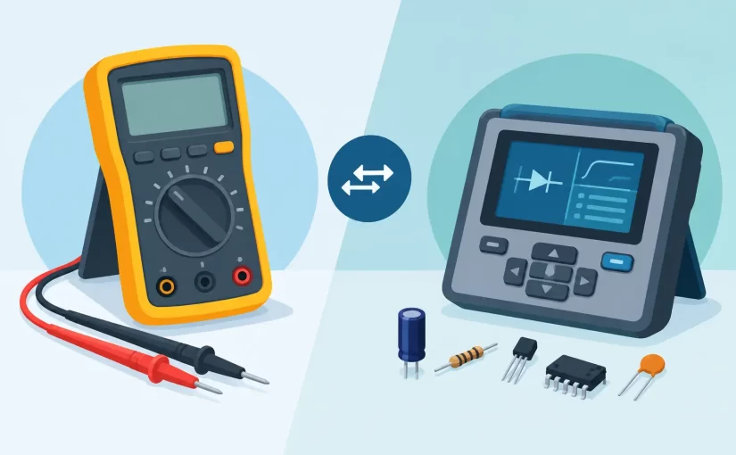
A failed 0402 capacitor does not announce itself with a convenient pair of test pads. On a densely populated board, the technician must reach a part, identify it, and decide whether its measured behavior is credible without losing time to lead placement or removing components prematurely. That is where the multimeter versus component analyzer decision becomes practical rather than theoretical.
A digital multimeter remains the first instrument many technicians reach for, and for good reason. It is the correct tool for verifying supply rails, continuity, voltage drops, current, diode junctions, and basic resistance. A component analyzer, particularly an LCR or ESR instrument with tweezer probes, addresses a different measurement problem: determining the value and electrical characteristics of a component quickly, often directly on the PCB.
Neither tool replaces the other. The correct choice depends on whether the fault is in the circuit’s operating conditions or in an individual component.
Multimeter versus component analyzer: the essential difference
A multimeter measures broad electrical quantities. In board-level troubleshooting, it answers questions such as: Is the 3.3 V rail present? Is this trace open? Is the fuse intact? Does this diode conduct in the expected direction? Is there a short between power and ground?
A component analyzer is designed to characterize parts. Depending on the instrument and mode, it can identify resistance, capacitance, inductance, ESR, impedance, dissipation factor, and sometimes component type. Advanced handheld instruments can also provide test frequencies appropriate for evaluating small capacitors and inductors beyond a simple low-frequency measurement.
This distinction matters because a component can pass a basic multimeter check and still be unsuitable in its circuit. A ceramic capacitor may not be shorted, but its capacitance may be far below value. An inductor may show continuity while its inductance is incorrect. A low-value resistor can be difficult to measure accurately with standard leads because probe and contact resistance become part of the result.
Where a digital multimeter remains the right first tool
For energized-board diagnostics, the multimeter is usually indispensable. It is designed to measure DC and AC voltage safely, and it can reveal whether a circuit section is receiving power before a technician begins evaluating individual parts. A component analyzer is not a substitute for verifying a regulator output, measuring a bias voltage, or checking current draw in series with a supply.
Continuity mode is also highly effective for locating broken traces, damaged connectors, open fuses, and solder-joint failures. Diode mode provides a fast comparison method for semiconductor junctions and parallel devices. These are circuit-level tests, not component-characterization tests.
A multimeter is also often the better choice when measurement category, input protection, and a wide voltage range are required. Professional troubleshooting starts with safety and with an understanding of the circuit state. Before touching an unpowered board with an LCR or ESR instrument, discharge capacitors and confirm that no external supply is present.
The limitation is resolution at the component level. Standard probes can slip on fine-pitch pads, bridge adjacent SMD parts, and add variable contact resistance. The meter may display resistance, capacitance, or diode behavior, but its available test conditions may not match the conditions that expose the suspected failure.
What a component analyzer adds to PCB work
A component analyzer shortens the path from suspected part to usable measurement. With tweezer-style probes, an operator can contact both ends of an SMD resistor, capacitor, or inductor directly. The instrument can identify the component category and display the relevant value without changing leads or manually selecting a function in many cases.
That workflow is especially valuable during incoming inspection, rework verification, repair of consumer and industrial electronics, and production troubleshooting. Instead of removing a part simply to read its value, a technician can obtain an initial in-circuit result in seconds. The result may not always be the final answer, but it is often enough to prioritize the next diagnostic step.
Frequency is one of the major differentiators. Capacitance and inductance are not fixed, context-free numbers. Their measured behavior changes with test frequency, bias, parasitics, and construction. A meter limited to a basic capacitance function may confirm a gross failure but may not provide useful discrimination among small, high-frequency components. Instruments offering 100 kHz or 250 kHz test frequencies can provide more relevant characterization for many SMD capacitors and inductors used in modern electronics.
ESR measurement is another example. A capacitor can retain a nominal capacitance reading while excessive equivalent series resistance impairs filtering or switching-supply performance. Measuring ESR at an appropriate frequency gives repair personnel a more meaningful indication of capacitor condition than capacitance alone.
In-circuit measurements require judgment
The phrase in-circuit measurement needs a qualification. A component analyzer measures the electrical network presented at its probes, not a magically isolated part. Parallel resistors, bypass capacitors, semiconductor paths, and nearby circuitry can alter the displayed value.
For example, a 10 kOhm resistor may read lower because another resistance path exists in parallel. A capacitor may read higher than expected when neighboring capacitors share the same rail. An inductor measurement can be affected by its surrounding switching converter circuitry. A correct reading in circuit is useful evidence, but an unexpected reading is not automatically proof that the contacted component has failed.
Experienced technicians use comparison. Measure an identical channel, a known-good board, or the same component position in a repeated circuit section. If the suspected capacitor reads 2.1 uF while equivalent locations read near 10 uF, the result is actionable even if the exact in-circuit value differs from the marking or schematic value.
When accuracy is critical, isolate one terminal or remove the part. This is not a weakness of the instrument. It is a property of network measurement. The best workflow uses rapid in-circuit screening first, then isolates only the parts that require confirmation.
Probe geometry can matter as much as accuracy
A published basic accuracy specification is necessary, but it is only part of real-world measurement quality. On 0201, 0402, and fine-pitch components, the ability to make stable, repeatable contact determines whether that specification can be achieved at the board.
Traditional test leads are flexible and universal, but they require two hands or a fixture and can obscure the target. Tweezer probes place both contacts under controlled spacing, improving access to small parts and reducing the risk of probing adjacent pads. This can materially improve throughput when hundreds of component checks are required.
For low-resistance work, contact resistance and lead compensation are equally significant. A reading of a few tenths of an ohm can be dominated by the test setup unless the instrument provides appropriate compensation and the operator maintains clean, firm contact. For precision work, verify calibration status and use an instrument supplied with a NIST-traceable calibration certificate when documentation is required by a quality system.
Siborg Systems instruments such as Smart Tweezers and LCR-Reader models are built around this direct-contact workflow, combining automatic component recognition with handheld LCR measurement for loose and board-mounted parts. Model selection should still follow the work: higher test frequency, Bluetooth data transfer, oscilloscope capability, or Analog Signature Analysis are valuable when they support the actual diagnostic process rather than merely adding functions.
Choosing the instrument for the failure mode
Use a multimeter when the immediate question concerns voltage, current, continuity, a power path, or a semiconductor junction. It establishes whether the circuit is powered correctly and whether obvious opens or shorts exist. It is the general-purpose foundation of every electronics bench and field kit.
Use a component analyzer when the question concerns the value or health of a resistor, capacitor, inductor, or other discrete component, especially a small SMD device. It is the faster choice when lead placement, measurement frequency, ESR, component identification, and repeatability on populated PCBs determine diagnostic speed.
For difficult faults, use both in sequence. Check the rail and circuit condition with the multimeter. Then use the analyzer to compare suspect components against expected values or a known-good reference. If the readings conflict with the schematic or with equivalent channels, isolate the part and measure it again.
The useful instrument is the one that reduces uncertainty at the next decision point. Keep the multimeter ready for circuit-level facts, and keep a component analyzer within reach when the diagnosis narrows to the parts themselves.