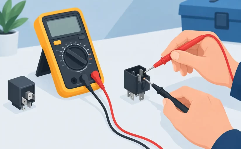
A relay can click positively and still fail under load. Pitted contacts, a weak coil, oxidized terminals, or an intermittent PCB solder joint can leave a control circuit unreliable while a quick continuity check appears normal. Knowing how to test relays means verifying the coil, the contact states, and the relay’s behavior at its rated operating voltage.
For repair, production, and field diagnostics, test the relay out of circuit whenever practical. A populated board can create parallel paths through drivers, suppression diodes, lamps, motors, and other loads that make otherwise valid measurements misleading. When removal is not practical, use the schematic and relay pinout to isolate what the meter is actually measuring.
Identify the Relay Terminals Before Measuring
Do not rely on terminal position alone. Automotive, PCB, power, reed, latching, and signal relays can use very different pin arrangements. Read the marking on the relay case, then confirm the manufacturer’s datasheet or the board silkscreen. Identify the two coil terminals and the switching terminals: common, normally open, and normally closed.
A single-pole double-throw relay has a common terminal that connects to the normally closed contact when the coil is de-energized. When the coil is energized, common transfers to the normally open contact. A single-pole single-throw relay has only one switched path, usually normally open. Latching relays require special attention because their contact state remains after the coil pulse is removed.
Disconnect power before resistance or continuity measurements. Also discharge capacitors in the circuit. A relay may be low voltage, but the equipment around it may store hazardous energy or contain mains-referenced circuitry.
Tools for Testing a Relay
A digital multimeter with resistance, continuity, and DC voltage functions covers most relay checks. A regulated bench supply set to the relay’s rated coil voltage is the preferred way to verify operation off the board. Set an appropriate current limit before energizing an unknown relay.
For contact resistance and borderline faults, a meter capable of low-resistance measurement is more useful than a basic audible continuity function. Continuity only confirms that resistance is below a threshold set by the meter. It does not establish that a power relay contact can carry rated current with acceptably low voltage drop.
For compact PCB relays, fine probes or tweezer-style probes improve terminal access and reduce the chance of bridging adjacent pads. An LCR meter can also measure coil inductance, but inductance alone does not prove correct actuation or contact performance. Siborg handheld component instruments are particularly useful where relay terminals and surrounding SMD components must be probed directly on a dense board.
How to Test Relays: Coil Resistance and Isolation
With the relay de-energized and preferably removed from the circuit, measure resistance across the coil terminals. Compare the reading with the relay datasheet, if available. Coil resistance varies substantially by relay voltage, package, and coil power rating, so there is no universal acceptable value.
An open reading, often shown as OL or overload, usually indicates a broken coil winding, damaged lead, or failed internal connection. A reading near zero ohms can indicate a shorted winding, although low-voltage, high-current relay coils can legitimately measure only a few ohms. The useful question is whether the measured value is plausible for that specific relay and consistent with the specification.
If the relay is still installed, lift one coil lead when an accurate result matters. Semiconductor drivers, flyback diodes, and other parts connected across the coil can affect the reading. A diode across a DC coil also means polarity matters when applying an external supply. Reverse polarity may forward-bias the diode and create a near-short across the supply.
Check isolation between either coil terminal and the contact terminals. A conventional electromechanical relay should show very high resistance between these sections with no power applied. Any measurable low-resistance path suggests contamination, internal damage, or an incorrect terminal identification. Do not use a high-voltage insulation tester on a relay connected to sensitive electronics unless the circuit and component ratings specifically allow it.
Verify Normally Open and Normally Closed Contacts
Set the multimeter to resistance or continuity. With the coil unpowered, measure from common to normally closed. This path should be closed, usually with a resistance near the meter lead resistance for a clean small-signal relay. Common to normally open should be open.
Now energize the coil with its specified DC or AC voltage, as applicable. For a DC relay, begin at the rated coil voltage rather than guessing. The contact states should reverse: common to normally open should close, and common to normally closed should open.
A click is useful confirmation of mechanical movement, but it is not a complete test. Record the resistance of the closed contact path before and after actuation. First short the meter probes together and note their resistance. If a relay measures substantially above that baseline, inspect for burned or oxidized contacts. The acceptable value depends on relay type. Signal relays may be specified in milliohms, while a worn power relay may still pass a basic continuity test yet cause enough voltage drop to prevent a motor, heater, or solenoid from operating correctly.
Test Pickup, Dropout, and Actual Coil Drive
A relay can pass a bench test and still fail in equipment because the driver circuit cannot deliver enough coil voltage or current. Measure voltage directly across the coil terminals while the circuit commands the relay on. Compare this value with the relay’s rated coil voltage and pickup specification.
Low coil voltage can result from a weak transistor or MOSFET driver, a poor ground, corroded connector, damaged trace, current-limited control module, or excessive supply sag. If the coil is powered through a transistor, measure the voltage across the driver as well. A high voltage drop across a saturated switching transistor points to a driver or control problem rather than the relay.
On a bench supply, slowly increase coil voltage while observing the contact transition. The pickup voltage is the point at which the relay changes state. Reduce the voltage to find dropout. Compare both values to the datasheet, recognizing that temperature and relay orientation can affect the result. Do not hold a relay coil above its rated voltage in an attempt to force operation. Overdrive can overheat the winding and create a new failure.
For intermittent faults, gently flex the relay pins and board area while monitoring coil voltage and contact continuity. Cracked solder joints at relay terminals are common in equipment exposed to vibration, heat cycling, or high contact current. Inspect both sides of the PCB for ring cracks, darkened pads, and overheated traces.
Confirm Contact Performance Under Load
No-load resistance testing cannot reveal every contact defect. A relay that switches a few milliamps from a meter may fail when it must carry a motor inrush current, lamp load, or inductive solenoid current. When safe and appropriate, test the relay in a controlled circuit with a representative load.
Measure voltage drop across the closed contacts while current is flowing. A healthy closed contact should have a low drop relative to the circuit voltage. Excessive drop indicates contact resistance, which creates heat according to I²R. A relay carrying several amps can develop damaging heat from resistance that seemed insignificant during an ohmmeter check.
Use caution with mains-powered, high-current, and inductive loads. A fused test setup, suitable isolation practices, and correctly rated probes are required. If contact welding is suspected, disconnect power and verify whether normally open contacts remain closed when the coil is de-energized. Welded contacts are a replacement condition, not a cleaning opportunity in most sealed PCB relays.
Common Results and What They Mean
An open coil indicates a failed relay. Correct coil resistance with no movement at rated voltage suggests mechanical binding or insufficient applied current. A relay that clicks but has high closed-contact resistance usually has worn, contaminated, or burned contacts. Correct operation on the bench but not in the product usually directs attention to coil drive voltage, solder joints, connectors, or the load circuit.
Replacement should match more than coil voltage. Verify contact arrangement, contact current and voltage ratings, coil type, pin layout, switching speed where relevant, and required approvals. A substitute with a different coil current can overload a transistor driver, while a different footprint can create unreliable PCB mounting.
A disciplined relay test separates the coil, the contacts, and the control circuit into measurable sections. That approach finds the actual failed element quickly and prevents a good relay from being replaced when the fault is a weak driver, damaged trace, or load-side problem.