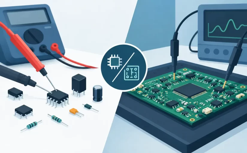
A 10 kΩ resistor that reads 2.3 kΩ on a populated PCB is not automatically defective. A parallel bias network, an IC input path, or a partially charged capacitor can all change the in-circuit result. That is the practical distinction behind component testing versus board testing: one method establishes a component’s own electrical condition, while the other evaluates how that component behaves within an operating circuit.
For PCB repair, manufacturing inspection, and failure analysis, neither approach replaces the other. The efficient workflow is knowing what each measurement can prove, what it cannot prove, and when a suspect part must be isolated before a repair decision is made.
Component Testing Versus Board Testing: The Core Difference
Component testing measures an individual device with its circuit influence removed or sufficiently isolated. The objective is to determine whether a resistor, capacitor, inductor, diode, transistor, LED, or other device meets its expected electrical parameters. Typical measurements include resistance, capacitance, inductance, ESR, diode forward voltage, leakage, and semiconductor junction behavior.
Board testing measures the assembled PCB as a system or as interconnected circuit sections. It may include power-rail resistance, voltage checks, current consumption, continuity, signal observation, functional test, or analog signature analysis. A board-level measurement is often faster because it does not require part removal, but it must be interpreted in the context of every parallel and series path connected to the test points.
The difference matters because an apparently incorrect in-circuit component value may be entirely normal. Conversely, a component that measures correctly when isolated can still fail under operating voltage, frequency, temperature, or load.
What Component Testing Can Establish
When a component is removed from the PCB, or when one terminal is lifted, its measured value is far more likely to represent the component itself. This is particularly useful for passive parts whose tolerance, ESR, or inductance is critical to circuit performance.
A capacitor can have the correct nominal capacitance yet still cause a switching supply to fail because its ESR has risen. An inductor may show continuity on a multimeter but have a reduced inductance value or a damaged core. A diode may pass a basic diode-mode test while displaying excessive leakage at its normal reverse voltage. Isolated testing narrows uncertainty by removing the influence of adjacent circuitry.
For surface-mount work, direct access matters as much as meter accuracy. Fine-pitch probes can slip, bridge neighboring pads, or introduce unstable contact resistance. Tweezer-style LCR instruments allow the operator to contact both ends of an SMD component directly, reducing handling time when sorting loose parts, checking rework, or verifying a suspected passive device.
Test frequency is also part of the measurement decision. A capacitance or inductance value measured at a low frequency may not represent behavior in a high-frequency circuit. Instruments with 100 kHz or 250 kHz LCR test capability can provide more relevant results for small SMD inductors, ceramic capacitors, RF-adjacent networks, and switch-mode power designs. The appropriate frequency depends on the component specification and the circuit application, not simply on the highest available setting.
What Board Testing Reveals Faster
Board testing begins with the question that matters to the equipment owner: why does the assembly not operate as expected? The answer is often found more quickly through system-level evidence than through removing and measuring parts one at a time.
A shorted power rail, missing clock, incorrect reference voltage, abnormal startup current, or distorted analog waveform can identify the failed section before any component is desoldered. Measuring voltage drop across a current-sense resistor, for example, may reveal an overload condition that is invisible in an unpowered resistance check. Observing a switching node can expose a controller that is attempting to start and immediately entering protection.
In-circuit LCR and ESR measurements are valuable screening tools. A capacitor that reads near zero ohms across the rail may point to a shorted ceramic capacitor or semiconductor device. A resistor that reads open may indicate a cracked part, damaged trace, or lifted pad. These results are actionable, but they are not always final proof of an individual component failure.
Board-level methods are particularly effective when the suspected problem involves interaction between devices. A regulator can test normally outside the board but shut down because a downstream rail is overloaded. A logic device may have good static supply resistance but fail only after thermal expansion. A connector may have continuity during a bench check and open under vibration or mechanical strain.
In-Circuit Measurement Has Limits
The main limitation of board testing is that the meter sees the complete network, not a single part. Parallel resistors lower the apparent resistance. Semiconductor junctions create nonlinear paths. Capacitors can charge from the instrument’s test signal, causing readings to drift. Inductors, transformers, and ferrite beads can be affected by the surrounding circuit and by the selected test frequency.
A low reading across a capacitor is a common example. It may indicate a failed capacitor, but it can also reflect the input impedance of a connected IC, another capacitor in parallel, or a short elsewhere on the same rail. Replacing the first component that produces a low resistance reading is not a controlled diagnostic method.
Before making an in-circuit measurement, power must be removed unless the procedure specifically requires an energized board. Stored charge should be discharged safely, especially in power supplies and high-voltage assemblies. Then compare the reading with a known-good board, a symmetrical circuit channel, the schematic, or the design’s expected node behavior. Context converts a measurement into evidence.
When to Isolate a Component
Isolation is justified when an in-circuit result conflicts with the expected circuit condition or when the cost of a wrong replacement is high. Lift one terminal of a passive part when practical rather than removing the entire component. This preserves pad integrity, reduces rework time, and quickly determines whether the circuit was influencing the original reading.
For semiconductors, isolation may require more planning. Removing a BGA, QFN, or multi-pin device solely for a basic measurement can create more risk than value. First use rail resistance, diode-mode comparisons, local temperature checks, voltage measurements, and signal inspection to establish a strong failure hypothesis. Component removal should confirm a likely diagnosis, not substitute for one.
The same principle applies in production and incoming inspection. Loose components are best verified before assembly, where their measured parameters can be compared directly with purchasing specifications. Completed boards are better evaluated through defined test points, functional checks, and targeted in-circuit measurements. These are different quality-control tasks with different acceptance criteria.
A Practical Diagnostic Sequence
Start with visual inspection. Look for cracked MLCCs, discolored resistors, solder bridges, corrosion, missing parts, poor rework, and damaged connectors. Visual evidence is fast, but it does not replace measurement.
Next, test the unpowered board for obvious shorts, open fuses, rail-to-ground resistance anomalies, and damaged protection devices. Compare suspect rails with similar rails or a known-good assembly where available. Then power the board under a controlled current limit and measure the power rails, references, reset lines, and expected signals.
Only after locating the probable fault area should you use component-level measurements to confirm individual parts. A compact instrument that combines LCR measurement with ESR capability, oscilloscope functions, or analog signature analysis can shorten this sequence because it supports both isolated checks and board-level investigation from the same bench or field kit. Siborg Systems instruments are designed for this direct-access workflow, particularly on densely populated SMD assemblies.
Choosing the Measurement That Answers the Question
Use component testing when you need a defensible value for a resistor, capacitor, inductor, diode, or loose replacement part. Use board testing when you need to locate a fault domain, confirm operating conditions, or understand how multiple devices interact. Use both when the board measurement identifies a suspect but cannot separate that component from the circuit around it.
Accuracy and repeatability still matter at every stage. A 0.1% or 0.2% basic accuracy specification is useful only when probe contact, selected range, test frequency, calibration status, and circuit conditions are also controlled. For documented work, NIST-traceable calibration provides confidence that the instrument itself is not the unknown variable.
The fastest repair is rarely the one that removes the first suspicious part. It is the one that uses board evidence to narrow the search, isolates components only when required, and leaves a clear measurement trail for the next technician.