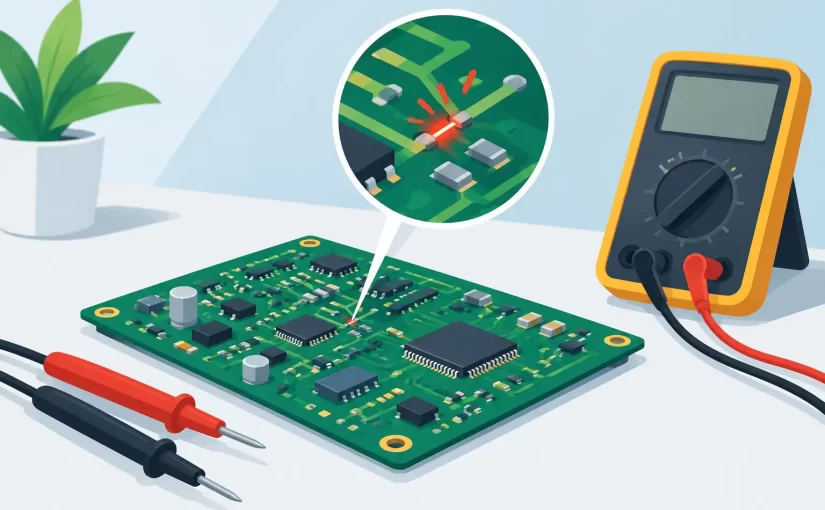
A board that pulls a bench supply into current limit before it boots has a short-circuit problem until measurements prove otherwise. Knowing how to diagnose board shorts means separating a genuine low-resistance fault from a normal low-impedance power rail, then locating the component or copper path responsible without damaging the PCB further.
A direct short is rarely solved by visual inspection alone. Modern boards may contain dense bypass capacitor networks, low-ohm regulators, processors with low core-rail resistance, and multilayer power planes. An effective process uses controlled power, comparative measurements, and component-level verification.
Confirm That the Board Actually Has a Short
Start with the board unpowered and disconnected from batteries, adapters, and external equipment. Measure resistance from the suspect rail to ground at a convenient test point, fuse, input capacitor, or connector pin. Record the reading and the meter polarity if diode mode will be used later.
A reading near 0 ohms is strong evidence of a short, but the exact threshold depends on the rail. A 12 V input commonly has a relatively high resistance to ground. A 1.0 V processor core rail may measure only a few ohms, or less, because it supplies many IC die structures in parallel. Treat a low resistance reading as a symptom, not a final diagnosis.
Compare against a known-good board when one is available. This is often the fastest way to determine whether a 2-ohm reading is expected. If no reference board exists, identify the rail from the schematic, board markings, or regulator output and consider what it powers before applying voltage.
Check the Input Path First
When the short is on the primary input, inspect input capacitors, protection diodes, transient voltage suppressors, reverse-polarity MOSFETs, and switching regulator MOSFETs. These components experience connector wear, reverse connection events, surge energy, and hot-plug transients.
Do not overlook conductive contamination. Moisture, flux residue, metal fragments, carbonized PCB material, and damaged connector pins can create a path that is intermittent or only appears at elevated voltage. Clean and dry the area before deciding that an IC has failed.
Build a Measurement Baseline
Resistance mode is useful for finding obvious rail-to-ground shorts, but diode mode often provides more diagnostic detail. Measure from ground to the rail and then reverse the probes. Semiconductor junctions, ESD structures, and regulator paths can produce different readings in each direction. Record values instead of relying on memory.
For boards with several rails, create a small table with the rail name, resistance to ground, diode-mode reading in both directions, and whether the rail is isolated by an inductor, fuse, or zero-ohm link. This turns troubleshooting into a repeatable process rather than a series of guesses.
Capacitance and ESR measurements can also help when examining suspect bypass capacitors removed from the circuit. A capacitor that reads as a direct short after removal is defective. However, an in-circuit capacitance reading does not prove an individual capacitor is good because parallel components affect the result.
Isolate the Short by Sections
The fastest repair method is usually division. Identify components that separate the affected rail into regions: inductors, ferrite beads, current-sense resistors, fuses, jumpers, and load switches are particularly useful boundaries.
Measure resistance to ground on both sides of the separator. If the regulator side is normal and the load side is low, the fault is downstream. If the low reading remains on the regulator side, investigate the converter, its input capacitors, and nearby switching devices.
Removing an inductor is often more informative than removing random capacitors. It isolates a power domain with one controlled operation and can prevent current injection from energizing sensitive sections unnecessarily. Document its orientation and value before removal, especially when working with visually similar ferrite beads and inductors.
Use a Schematic, but Verify the Layout
A schematic identifies electrical connectivity; the PCB layout shows where heat and current will appear. A rail may feed dozens of capacitors spread across both sides of a multilayer board. Follow the power-plane topology and locate all components connected to the isolated node.
If documentation is unavailable, continuity measurements and board markings can still establish the path. Probe from the rail test point to capacitor pads, coil terminals, and IC decoupling capacitors. A fine-tip tweezer-style instrument is valuable here because it can contact small SMD terminations directly without slipping across adjacent pads.
Find the Fault With Controlled Current Injection
Once the suspect section is isolated, inject a controlled low voltage into the shorted rail using a current-limited bench supply. Begin at a low voltage, commonly 0.5 V to 1 V, and use only enough current to create a detectable thermal signature. The correct voltage and current depend on the rail and components attached to it.
Do not inject a voltage higher than the rail rating. Avoid powering a battery rail through an unknown path, and be cautious with rails connected to sensitive IC outputs or unisolated switching converters. If the board contains a large capacitor bank, allow time for it to discharge before moving probes or removing parts.
A failed ceramic capacitor may warm quickly. A shorted IC can heat across a larger package area. Use a thermal camera when available, or apply a small amount of isopropyl alcohol and observe where evaporation occurs first. Freeze spray can provide the opposite effect: the fault location may melt or discolor the frost earlier than surrounding components.
Thermal methods are powerful but not absolute. Copper planes spread heat, and the component that becomes warmest is not always the failed component. It may simply be the first low-resistance part encountered along the plane. Confirm the finding with isolated measurements before replacement.
Test Suspect Components Directly
Multilayer ceramic capacitors are among the most common causes of hard rail shorts. Check them for continuity after removal. If the short disappears when a capacitor is lifted, measure the removed part and then recheck the rail before installing a replacement.
For MOSFETs, measure drain-to-source resistance and diode behavior with the board unpowered. A low reading in both directions may indicate a failed device, though parallel circuitry can complicate the result. Isolate at least one terminal when the in-circuit reading is ambiguous.
Regulator ICs require more judgment. A shorted output can be caused by a failed regulator or by its load. After removing the output inductor or load switch, test each side independently. Replacing the regulator first may waste time and can obscure the original failure mechanism.
For small SMD components, Siborg Smart Tweezers can identify resistance, capacitance, inductance, and ESR directly at the component leads, reducing handling time during verification. Use in-circuit readings as screening data, then isolate the component when parallel paths prevent a conclusive result.
Avoid Common Diagnostic Errors
Several habits extend board-short repairs unnecessarily:
- Applying full input voltage before identifying the shorted rail can destroy components that survived the original fault.
- Removing capacitors at random changes the circuit without producing useful evidence.
- Treating every low-ohm rail as defective leads to false diagnoses on processor, FPGA, and memory supplies.
- Trusting a single resistance reading ignores diode direction, temperature, meter test current, and parallel circuit paths.
- Replacing a visibly damaged part without checking upstream and downstream sections can leave the root cause in place.
After replacing the failed component, repeat the baseline measurements before restoring normal power. Bring the board up on a current-limited supply, observe startup current, verify each rail in sequence, and test the original functional symptom. A rail that is no longer shorted but has incorrect regulation is not yet repaired.
The most reliable board-short work is methodical: establish the rail behavior, isolate the power domain, inject only controlled energy, and verify the suspect part outside of misleading parallel paths. That approach protects the board and produces a repair result that can be measured, documented, and repeated.