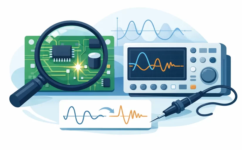
A board can look intact, pass a basic continuity check, and still fail because one semiconductor junction is leaky, one IC pin is shorted, or one parallel path no longer behaves like the reference circuit. Analog signature analysis gives technicians a practical way to see those differences before applying power. Rather than reporting a single resistance, capacitance, or diode-drop value, it displays the voltage-current relationship of a circuit node as a recognizable trace.
For PCB repair, production troubleshooting, and incoming inspection, that visual comparison can reduce the time spent isolating faults hidden by parallel components and complex semiconductor networks. It is especially useful when a known-good board, matching channel, or repeated circuit section is available for comparison.
What Analog Signature Analysis Measures
Analog signature analysis, often called ASA or VI signature analysis, applies a controlled AC stimulus between a probe point and circuit common on an unpowered board. The instrument observes the resulting voltage and current, then plots them against one another. The displayed pattern is the component or network signature.
A purely resistive path produces a straight diagonal line. A capacitor produces an elliptical trace because current leads voltage. Inductance changes the ellipse in the opposite direction. Diodes and transistor junctions create nonlinear shapes with knees, arcs, or asymmetric halves. A complex IC pin may produce a signature that is not easily assigned to a single textbook component, but it can still be highly repeatable on a healthy board.
That distinction matters. ASA is not intended to replace an LCR measurement, ESR test, oscilloscope capture, or powered functional test. It is a comparative diagnostic method. Its strength is showing that a node behaves differently from its expected electrical signature.
Why One Reading Is Often Not Enough
A digital multimeter is indispensable, but its resistance and diode-test modes usually provide one operating point. An LCR meter measures selected component parameters at defined test conditions. Both results are valuable, yet neither necessarily shows how a populated circuit path responds across a changing applied voltage.
Consider an IC input protected by clamp diodes. A meter may report a plausible diode value in one direction and overload in the other. ASA can reveal whether the expected clamp action occurs symmetrically, whether a junction begins conducting too early, or whether a leakage path has altered the shape. The comparison becomes more useful when the same point is measured on a working board.
The method also helps where in-circuit measurements are ambiguous. A resistor in parallel with other components may not measure near its marked value. A capacitor may be connected to semiconductor junctions, power rails, and neighboring circuitry. Instead of treating every nonstandard reading as a bad part, compare the complete node signature to a known-good equivalent. If the traces agree, the network is probably behaving as designed.
How to Use Analog Signature Analysis on a PCB
Start with power removed and stored energy discharged. This is a low-energy diagnostic method, not a powered-circuit test. Remove batteries, disconnect external supplies, and discharge large capacitors according to the equipment procedure. Verify the board is safe to probe before connecting an ASA instrument.
Choose a stable reference point, usually circuit ground, and probe the suspect node. For a first pass, use a test level that provides readable traces without forcing conduction through circuitry that does not normally see that stress. Test amplitude, source resistance, and frequency influence the displayed signature, so comparison measurements must use identical settings.
The most productive approach is comparison probing. Measure the same node on a known-good board, an identical board section, or a repeated channel. Differential amplifier stages, LED driver channels, multi-phase power sections, and replicated I/O circuits are well suited to this process. A mismatch in shape, tilt, symmetry, or trace width is a reason to investigate further, not automatic proof that the nearest component has failed.
When no reference board exists, compare related nodes and use the schematic or board layout to understand what is connected. This takes more interpretation. A signature that looks abnormal in isolation may be correct for a node tied to protection devices, pull-up networks, or internal IC structures.
Read the Shape Before Naming the Fault
A trace collapsed near the vertical axis suggests a low-impedance path or short. A trace close to the horizontal axis suggests a high-impedance or open condition, although the selected range and source impedance must be considered. A shifted or widened ellipse can indicate changed capacitance, ESR, leakage, or an additional parallel path.
Asymmetry is often the most revealing clue. If one half of a trace differs from the other, look for a diode, transistor junction, MOSFET body diode, TVS device, or IC input-protection structure. If the healthy reference has a clean knee and the suspect board has a rounded, early-conducting curve, leakage or junction damage becomes plausible.
Do not interpret a signature without considering the circuit around it. A shorted ceramic capacitor may create a near-vertical trace, but so can an intentionally low-value resistor or a power rail with many parallel loads. An apparently open node may be isolated by a switch, relay, or logic state that is normal when the board is unpowered.
Selecting Test Conditions Matters
ASA results are only as comparable as the conditions used to create them. Increasing stimulus voltage can turn on semiconductor junctions that remain invisible at lower levels. Changing source resistance limits current differently and can alter the slope or knee of a trace. Test frequency changes the response of capacitive and inductive paths.
This is not a weakness. Adjustable conditions let an experienced user expose faults that a single fixed test cannot reveal. The trade-off is discipline: record the settings used for a good-board signature, then duplicate them precisely on the suspect board. A library of reference captures becomes substantially more useful when it includes board revision, probe location, ground point, and test conditions.
For small surface-mount work, probe control is equally important. Fine probes or tweezer-style contacts help prevent slipping onto adjacent pads and reduce hand-induced variation. On dense assemblies, use a fixed ground clip and approach test pads or component ends consistently. Repeatability is part of the measurement. Where ASA Fits With LCR, ESR, and Oscilloscope Tools
A practical bench workflow uses each instrument for what it does best. Use a high-accuracy LCR meter or the multi-function LCR-Reader-Pro to identify resistance, capacitance, inductance, impedance, and ESR. Use an ESR meter when electrolytic capacitor condition is the question. Use a DMM for voltage, continuity, diode checks, and general verification. Use an oscilloscope on powered equipment to examine timing, ripple, noise, and switching behavior.
Use analog signature analysis when the board is unpowered and the fault is likely hidden in a network, semiconductor path, or unknown in-circuit interaction. It can narrow a large search area before powered testing, which is valuable when powering a damaged board could worsen a fault or obscure it through protection shutdown.
Advanced handheld instruments like the LCR-Reader-MPB, which combines high-accuracy LCR/ESR measurement, LED testing, oscilloscope modes, and built-in Analog Signature Analysis (ASA), reduce tool changes at the bench. Pair it with software integration or the LCR-Reader Smart LED Tester & ASA Module for extended visual signature capturing. Siborg Systems instruments are designed around this type of direct PCB access, pairing compact probing with measurement functions suited to discrete and surface-mount components. The right configuration still depends on required test frequency, basic accuracy, data capture needs, and the types of boards serviced.
Common Mistakes That Produce Misleading Signatures
The most common error is comparing unlike conditions. A different ground point, probe location, test range, or stimulus setting can create a visible difference even when both boards are good. Document the setup before drawing conclusions.
Another mistake is assuming every trace belongs to one component. On a populated board, the signature is usually the combined response of everything electrically connected to that node. Use board knowledge and comparison points to separate a true anomaly from normal circuit topology.
Finally, avoid probing powered circuits in ASA mode unless the instrument documentation explicitly permits it. External voltage can damage the instrument, distort the signature, or create a safety hazard. ASA is most effective as a controlled, unpowered test.
A useful signature does not have to identify the failed part immediately. Its job is to tell you where electrical behavior stopped matching the expected circuit. From there, targeted LCR, ESR, diode, continuity, and powered tests can turn a suspicious trace into a confirmed repair.
.