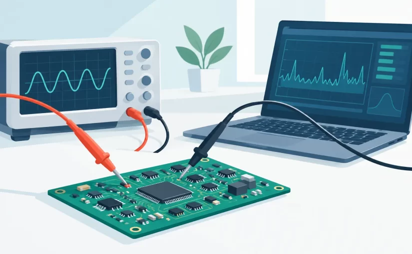
A board repair record that says “capacitor tested bad” is rarely useful six weeks later. A record that identifies the board revision, reference designator, test frequency, measured capacitance, ESR, bias condition, and instrument status can be checked, repeated, and defended. That distinction is central to how to capture measurement data when troubleshooting populated PCBs, qualifying incoming components, or documenting production results.
The objective is not to collect the largest possible number of readings. It is to capture readings that retain their measurement context. A value without test conditions may look precise while being impossible to compare with a later result.
Start with a defined measurement objective
Before placing probes on a component, determine what decision the measurement must support. A technician locating a shorted ceramic capacitor needs a fast comparison between rails or like circuits. A quality-control operator verifying an inductor lot needs controlled test frequency, fixture consistency, and acceptance limits. An engineer characterizing a circuit may need a time-based waveform in addition to L, C, R, or ESR values.
This objective determines the required instrument, range, test frequency, and record format. Resistance measured with a DMM is not interchangeable with impedance measured by an LCR meter. Likewise, a capacitance reading at 1 kHz may not predict behavior at 100 kHz or 250 kHz. For components used in switching supplies, RF-adjacent circuits, and high-speed bypass networks, frequency selection can materially change the useful result.
Record the expected value or acceptable range before testing when possible. This prevents a common troubleshooting error: treating the first displayed number as proof that a component is good.
Control the conditions before capturing data
Good data begins with a stable setup. Verify that the PCB is unpowered and discharged unless the procedure specifically requires powered-circuit measurements. Stored energy in capacitors can damage an instrument, distort readings, and create a safety hazard.
For loose components, use clean contacts and a repeatable fixture or probe position. For populated boards, identify all parallel paths before interpreting an in-circuit result. A resistor can appear lower in value because another circuit path is in parallel. A capacitor can appear larger or have a lower apparent ESR because other capacitors share the same rail. Semiconductors, IC protection structures, and leakage paths can also influence the result.
This does not make in-circuit measurement ineffective. It changes what the reading means. In-circuit readings are often highly effective for comparative diagnosis: compare an identical channel, a known-good board, or neighboring components of the same design. When the result is close to a decision limit, isolate one lead or remove the component for confirmation.
Environmental conditions also matter for close-tolerance work. Temperature affects resistance, capacitance, and semiconductor behavior. Allow the board and instrument to stabilize after moving from a cold service vehicle into a warm lab. Keep fingers away from exposed component terminals during high-resistance measurements, where body leakage can become part of the reading.
Select the measurement method that matches the component
The fastest measurement is not always the right measurement. Choose the mode and connection method based on the component and failure mode under investigation.
For resistors, confirm whether a simple DC resistance reading is sufficient or whether in-circuit paths require comparison or isolation. For capacitors, capture capacitance and ESR when both values affect the diagnosis. A capacitor may remain near nominal capacitance while its ESR has increased enough to cause ripple, startup, or regulation problems.
For inductors, record inductance at a relevant test frequency and note DC resistance if winding loss or open connections are concerns. For diodes and LEDs, capture forward voltage at a stated test current where the instrument supports it. A visual pass/fail result alone is not adequate for documenting marginal devices.
Tweezer-style LCR instruments are particularly useful for small SMD parts because they reduce lead length, contact uncertainty, and time spent positioning conventional probes. On densely populated boards, insulated probe arms and fine tips can help reach a component without bridging adjacent pads. The contact method should still be documented when measurements are close to specification, since oxidation, probe pressure, and contact point can alter low-value resistance and ESR results.
How to capture measurement data with useful context
A useful record combines the measured value with the information needed to reproduce it. At minimum, each entry should identify the board or assembly, location, component type, value, units, and test conditions. For professional troubleshooting and quality records, capture these fields consistently:
- Board model, serial number, revision, and work order or case number
- Reference designator and a brief component description
- Measurement function, test frequency, range, and equivalent circuit setting when applicable
- Measured result, units, tolerance limit, and pass, fail, or comparison status
- Instrument model, asset number, calibration status, date, and operator
The equivalent circuit setting deserves attention. LCR meters may present series or parallel values, such as Cs-Rs or Cp-Rp. Neither is universally correct. A low-impedance capacitor at higher frequency is often better represented by a series model, while a high-impedance component may be better represented by a parallel model. The key is to select the appropriate model for the application and use it consistently across comparable readings.
Do not round away diagnostic information too early. If the instrument reports 0.184 ohms ESR, recording “0.2 ohms” may be adequate for a broad service note but not for a trend record. Save the native resolution where the measurement uncertainty supports it, then apply the acceptance limit separately.
Use digital transfer to reduce transcription errors
Manual recording remains practical for a handful of readings, but it becomes a source of errors when testing boards in quantity. Transposed decimal points, missing units, and undocumented settings can make a spreadsheet less reliable than the meter display it was copied from.
Bluetooth-enabled measurement tools provide a more controlled path for repeated work. On compatible instruments, captured readings can be transferred to a mobile device or PC while retaining timestamps and reducing manual entry. Siborg Systems instruments such as Bluetooth-enabled Smart Tweezers and LCR-Reader models are designed for component-level measurement workflows where direct access and digital transfer both matter.
Digital capture is most valuable when the receiving format is standardized. Use fixed fields for board ID, reference designator, measurement type, limits, and technician notes. If a measurement is tied to a photo, thermal image, or oscilloscope capture, use the same work-order identifier across every file. That creates a record that can be reviewed without guessing which board or test point the data belongs to.
For small repair operations, a structured CSV file may be sufficient. For production or calibration-controlled environments, integrate readings into the existing quality system and preserve revision history. The best method depends on volume, traceability requirements, and whether the data will be used for trend analysis rather than a single repair decision.
Verify the instrument and the data
A precise display does not guarantee a valid measurement. Inspect probe tips, leads, and tweezer arms for contamination, wear, looseness, or damaged insulation. Perform open and short compensation when the instrument and procedure require it, especially when measuring low impedance or using extension fixtures. Compensation removes a portion of fixture and lead effects, but it cannot correct poor component contact or a wrong test method.
Maintain calibration records appropriate to the work. A NIST-traceable calibration certificate supports documented quality processes and establishes confidence in the instrument’s performance at the time of calibration. It does not eliminate the need for a quick functional check before critical work. A known reference component or verification standard can reveal damage or setup problems between scheduled calibrations.
Review outliers before acting on them. Repeat the measurement after repositioning the probes, then compare with a known-good location or board. If the reading changes significantly, investigate contact quality, parallel circuitry, temperature, and test settings before declaring the component defective.
Turn measurements into repeatable decisions
Capture a baseline from known-good boards whenever a product family is serviced repeatedly. Baseline records are more useful than generic nominal values because they include the realities of the assembled design: tolerance stack-up, parallel networks, and normal production variation.
Over time, this turns measurement capture from documentation into a diagnostic tool. A recurring ESR shift on a certain rail, a gradual change in coil resistance, or a pattern of low LED forward voltage can reveal failure modes before they are obvious from a single board.
The next time a component reading drives a repair or release decision, capture the conditions that produced it along with the number. A measurement record should let another technician recreate the test, understand the result, and move directly to the next justified action.