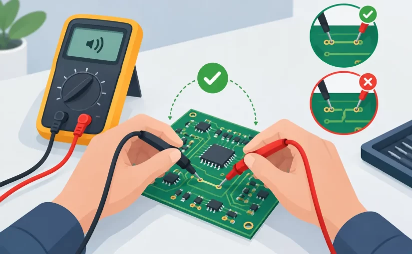
A continuity beep is useful only when it answers a specific question. On a populated board, adjacent nets may be connected through low-resistance components, IC protection structures, relay contacts, or parallel circuitry. Knowing how to check PCB continuity means proving the intended conductive path while recognizing when an audible indication is not sufficient evidence.
For PCB repair, production inspection, and field service, continuity testing is primarily used to find open traces, cracked vias, poor solder joints, damaged connector paths, and unintended shorts. The meter is simple. The interpretation requires a method.
What PCB Continuity Testing Actually Verifies
Continuity mode applies a small test signal between two probes and indicates that the resistance is below the instrument’s continuity threshold. Depending on the meter, that threshold may be anywhere from a few ohms to several tens of ohms. A beep therefore means low resistance, not necessarily a direct copper short.
This distinction matters on dense assemblies. A 0-ohm jumper, inductor, fuse, relay contact, low-value current-sense resistor, or power distribution network can all produce a valid continuity indication. Conversely, a corroded trace or marginal solder joint may measure several ohms and fail to trigger the buzzer even though some electrical connection remains.
Use continuity mode for fast go/no-go checks. When the result affects a repair decision, switch to resistance mode and record the reading. A stable resistance value provides more diagnostic information than a beep alone.
Set Up the Board and Meter Correctly
De-energize the PCB before connecting a continuity tester. Disconnect the main supply, battery, USB connection, external programmer, and any source that can backfeed the board. Continuity mode is not intended for measurements on live circuits, and external voltage can damage the meter or produce misleading results.
Large capacitors deserve special attention. After power is removed, verify that bulk capacitors and high-voltage sections have discharged. Use the correct discharge procedure for the equipment and its stored energy. Do not intentionally short a charged capacitor with a probe tip.
Inspect the test leads before blaming the PCB. Touch the probe tips together and observe both the audible response and displayed resistance. A professional DMM should show a low, repeatable value, but the exact result includes lead and contact resistance. Flex the leads near the strain reliefs while testing. Intermittent leads can imitate an intermittent board fault.
For fine-pitch work, standard pointed probes are often too large. Sharp micro-probes, pogo probes, or tweezer-style contacts reduce the chance of bridging neighboring pads. The goal is controlled contact on the intended copper feature, not simply obtaining a beep.
How to Check PCB Continuity Step by Step
Start with the schematic, board layout, assembly drawing, or a known-good board whenever possible. Define the net you expect to follow. For example, you may need to verify a signal from a connector pin to a series resistor, from that resistor to an IC pin, and from the IC pin through a via to another layer.
Place one probe on a known point on the net, such as a connector terminal, test point, component pad, or exposed via. Place the second probe at the expected destination. Hold both probes steadily and wait for the reading to settle. Oxidized pads, conformal coating, flux residue, and probe movement can cause momentary or unstable results.
If continuity is present, move the second probe along the signal path. Check both sides of series components, each accessible via, and each connector transition. This divides the net into smaller sections and localizes the fault quickly. A good connection up to one via and an open reading after it identifies the region that needs magnification and inspection.
If continuity is absent, do not immediately scrape solder mask or replace a component. First confirm that the two points are intended to be on the same net. Then inspect for a series resistor, ferrite bead, fuse, switch, transistor junction, or connector contact between them. The open reading may be correct by design.
When testing a suspected short, place probes on the two nets that should be isolated. A low reading may indicate a solder bridge, conductive contamination, damaged IC, failed capacitor, or an alternate path elsewhere in the circuit. Compare the resistance with an equivalent channel or a known-good assembly if available.
Test the Most Common Failure Points
Traces and vias
A trace can look intact while being open beneath a component, inside a flex region, or under corrosion. Test from one end of the trace to the other, then test at intermediate points. For multilayer boards, test each via from its top-side land to the corresponding bottom-side land where accessible.
A via may be mechanically present but electrically unreliable because of barrel cracking or poor plating. Flexing the board is not a preferred test method because it can worsen the damage. Instead, monitor resistance while applying only minimal, controlled pressure near the suspect area.
Solder joints and SMD pads
Continuity between a component lead and its pad confirms little if the pad itself has lifted from the trace. Test from the component terminal to a downstream via or another point on the same net. On small surface-mount devices, direct tweezer contacts can be faster and more repeatable than trying to balance two conventional probes on adjacent terminations.
For components with multiple parallel connections, isolate the question. Test a resistor pad to its trace, then test across the resistor separately. This prevents the component value from being confused with the integrity of the copper path.
Connectors, cables, switches, and fuses
Connector faults often occur at the solder tail, crimp, plated contact, or cable strain point. Test pin-to-pin while gently moving the cable or operating the mating mechanism. A reading that changes with movement is evidence of an intermittent mechanical connection.
For switches and relays, compare the measured state with the specified contact state. Closed contacts should have low and stable resistance. If the meter beeps but the resistance is higher than expected for the application, measure it quantitatively. A few ohms may be unacceptable in a power path even though continuity mode reports a connection.
A fuse should normally show near-zero resistance in circuit. If a low value is questionable because of parallel circuitry, lift one end or use the board documentation to identify alternate paths.
Avoid False Positives on Populated Boards
Semiconductor junctions are a common source of confusion. Depending on probe polarity and meter test voltage, an ESD diode or transistor junction can conduct in one direction and appear open in the other. Reverse the probes and compare the behavior. Use diode-test mode when the question is junction behavior rather than copper continuity.
Capacitors can briefly conduct as they charge from the meter’s test source. The display may start low and rise, or the buzzer may chirp momentarily. Wait for the reading to stabilize. A persistent low resistance across a power rail is more suspicious than a transient indication, but even that requires comparison against the design and nearby circuit sections.
Parallel paths are unavoidable in many circuits. A signal may return through an IC, a pull-up network, a transformer winding, or another channel. If the board architecture is complex, isolate the path by removing a connector, opening a jumper, lifting one component terminal, or testing an unpopulated equivalent board. Isolation is slower, but it turns an ambiguous result into a defensible measurement.
Select the Right Instrument and Probe Method
A digital multimeter is the primary tool for continuity work, provided its beeper response is fast enough and its resistance range is appropriate for low-ohm verification. For boards with very small components, probe geometry can have more effect on speed than the meter itself.
SMD test tweezers are particularly effective for measuring directly across chip resistors, fuses, inductors, and capacitors without chasing small pads with separate leads. An LCR meter or ESR meter does not replace continuity mode, but it adds component-level evidence when a part appears electrically connected yet behaves incorrectly in circuit. For example, a shorted multilayer ceramic capacitor and a normal low-resistance power rail require different follow-up tests.
Siborg’s handheld tweezer-style instruments are designed for direct contact with small SMD terminations, helping technicians separate a trace fault from a component fault without unnecessary board handling. For documented service work, use calibrated instruments and record readings when acceptance criteria require traceability.
When Continuity Is Not Enough
Continuity testing cannot confirm current-carrying capability, insulation performance at operating voltage, high-frequency signal integrity, or the health of a component under load. A cracked trace may pass a low-current meter test and fail when the circuit draws current. A connector contact may read low resistance at rest but develop voltage drop under vibration or load.
Follow a successful continuity check with the test that matches the failure mode. Measure voltage drop for power paths, use four-wire resistance measurement for very low-resistance connections, perform insulation testing where safety requirements apply, or examine high-speed signals with an oscilloscope. Continuity narrows the fault location. It does not replace functional verification.
The most efficient PCB troubleshooting habit is to treat every beep as a data point, not a verdict. Test the intended net, compare the resistance to the circuit expectation, and isolate uncertain paths before rework. That approach protects pads, reduces repeat repairs, and produces measurements that can be trusted.