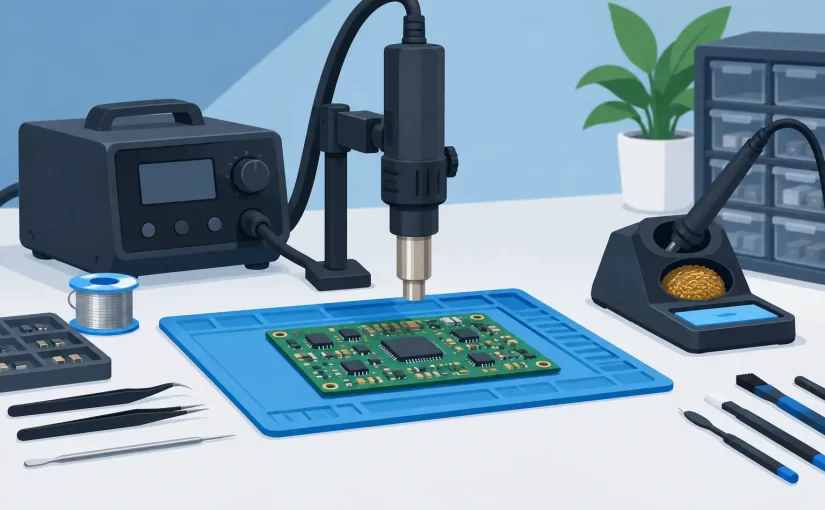
A 0402 capacitor can be removed in seconds and still leave a repair that fails under load. The difference is rarely just operator skill. The best tools for SMD rework give the technician control over heat, access, alignment, and verification before the board returns to service.
SMD rework is a system, not a single tool purchase. Hot air without stable board support can lift pads. A fine soldering iron without proper magnification can bridge adjacent pins. A replacement component selected only by its marking can introduce a fault that looks identical to the original failure. Build the bench around the component sizes, board density, and volume of work you actually handle.
Best Tools for SMD Rework: Start With Heat Control
A temperature-controlled soldering iron is the primary tool for resistors, capacitors, jumpers, small diode packages, and touch-up work. Select a station with fast thermal recovery and cartridges or tips suited to the work, rather than relying on one ultra-fine conical tip for everything. A small chisel or hoof tip transfers heat more efficiently to most pads and allows controlled drag soldering on fine-pitch leads.
For production-quality work, temperature stability matters more than a high maximum temperature rating. Excessive tip temperature oxidizes flux quickly, damages pads, and increases the chance of heat traveling into adjacent components. Start with a temperature appropriate for the alloy, tip geometry, ground-plane connection, and thermal mass of the joint. Adjust based on observed wetting performance, not habit.
A hot-air rework station is necessary for QFNs, SOICs, chip components, shielded areas, and parts with contacts underneath the package. Look for adjustable airflow as well as temperature control. High airflow can displace 0201 and 0402 parts long before the solder reaches reflow temperature. Low, directed airflow combined with a nozzle sized close to the package gives better local control.
Preheating becomes valuable when working on multilayer boards, large ground planes, heavy connectors, or lead-free assemblies. A board preheater reduces the thermal gradient between the top-side rework area and the rest of the PCB. This shortens hot-air exposure and reduces the risk of pad lifting, board warpage, and repeated heating of nearby components. It is not mandatory for every repair, but it pays for itself quickly on dense or thermally demanding boards.
Magnification and Lighting Prevent Expensive Rework
Inspection should happen before removal, after pad preparation, and after soldering. A stereo microscope remains the most practical option for manual rework because it provides depth perception. That makes it easier to position a QFN, inspect solder fillets, identify lifted lands, and judge whether a component is sitting flat.
A digital microscope is useful for documentation, training, and sharing images with a customer or engineering team. It may be less comfortable for continuous hand work if display latency or limited depth perception gets in the way. Many repair benches use both: a stereo microscope for placement and soldering, then a digital camera or microscope for records.
Use bright, adjustable illumination with minimal shadowing. Ring lights are common, but angled side lighting can reveal tombstoning, solder bridges, cracked terminations, and damaged traces that direct overhead light can hide. The goal is not maximum brightness. It is clear contrast at the working distance you use.
Board Holding and Hand Tools Matter More Than They Look
A stable PCB holder is one of the most effective upgrades for repeatable SMD work. It should secure the board without flexing it, allow access from multiple sides, and tolerate localized heat. Magnetic holders can be convenient, while adjustable edge clamps are better for irregularly shaped boards. Avoid clamping directly on delicate connectors, test points, or flex sections.
Precision tweezers are required for placement and removal, but tip selection should match the package. Very sharp tips are useful for fine-pitch work, while broader curved tips offer more secure control of 0603 and larger chip parts. ESD-safe construction is appropriate when handling sensitive semiconductors, and clean tips reduce the risk of contaminating pads with residue.
Keep a nonmagnetic spudger, fine picks, a scalpel or trace-cutting knife, and small flush cutters available for repair tasks. These are not substitutes for proper heating. They are support tools for removing adhesive, separating a component after solder has reflowed, repairing solder mask edges, or preparing a damaged trace.
When a board must be held at an angle, use a fixture that does not force your hands into an awkward position. Poor ergonomics shows up as shaky placement, inconsistent iron contact time, and damaged pads during long repair sessions.
Flux, Solder, and Consumables Set the Process Window
No-clean flux is a practical default for many board repairs, but flux type should be chosen for the assembly and cleaning requirements. Tacky flux keeps small parts from moving during hot-air work. Liquid flux is useful for drag soldering and for improving heat transfer during component removal. Water-soluble flux can be highly active, but residues must be cleaned thoroughly.
Use solder wire sized for the work. Fine wire gives better volume control on small pads; larger wire is more efficient for connectors and heavier joints. For lead-free boards, adding a small amount of compatible alloy or low-melting-point removal alloy can lower the effort needed to remove a part, but it must be fully removed from the pads before installing the replacement component.
Solder wick is essential for pad cleanup and bridge removal. Choose a width that matches the land pattern. Oversized wick can pull heat from the joint and increase the time the board is exposed to the iron. Used correctly with flux, it leaves flat, solderable pads without scraping or excessive abrasion.
Kapton tape and heat shields protect neighboring components during hot-air work. They help, but they are not a guarantee. Sensitive plastic connectors, microphones, switches, and electrolytic capacitors may still require local shielding, reduced airflow, or removal before rework begins.
Verify Components Before and After Installation
A successful solder joint does not prove the installed part is correct. This is where a dedicated LCR meter or SMD test tweezers become more useful than conventional test leads. Direct tweezer measurement lets the technician identify loose resistors, capacitors, inductors, and semiconductors quickly, with less risk of slipping across adjacent pads.
In-circuit readings require judgment. Parallel paths, semiconductor junctions, and surrounding capacitance can influence the value. Compare with a known-good channel or an equivalent location on the board when possible. If the result is ambiguous, lift one end of the component or test the replacement part before installation.
For high-frequency or low-impedance components, test frequency and basic accuracy affect whether a reading is meaningful. Instruments such as Siborg Smart Tweezers and LCR-Reader models are designed for direct SMD contact, with configurations offering up to 250 kHz test frequency, accuracy options down to 0.1%, and features such as ESR measurement. Those capabilities are especially relevant when verifying small capacitors, inductors, and low-value resistors where a basic multimeter cannot provide enough information.
A digital multimeter remains necessary for continuity checks, voltage rails, diode tests, and gross resistance faults. It complements, rather than replaces, a purpose-built LCR instrument. For difficult intermittent faults, oscilloscope capability and Analog Signature Analysis can add another layer of evidence before parts are removed unnecessarily.
Choose the Tool Set for the Job, Not the Catalog
A technician repairing consumer boards occasionally can begin with a controlled iron, compact hot-air station, quality flux, tweezers, microscope, board holder, and reliable measurement instrument. A service department handling multilayer industrial boards should add preheating, dedicated nozzles, documented calibration, ESD controls, and a workflow for recording measurements.
For fine-pitch IC replacement, component alignment and thermal control deserve more budget than specialty hand tools. For passive-component troubleshooting, fast and accurate direct measurement often has the largest effect on turnaround time. For high-volume rework, fixtures and repeatable thermal profiles become the priority.
The practical standard is simple: use enough heat to form or reflow the joint quickly, enough magnification to inspect it honestly, and enough measurement capability to prove the component and repair are correct. That approach produces fewer repeat repairs and gives every board a better chance of leaving the bench fixed for the right reason.