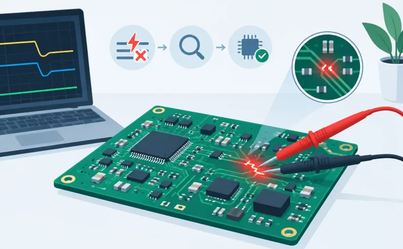
A board that draws 1.8 A from a 3.3 V bench supply before its processor can boot presents a familiar repair problem: the power rail is shorted, but the board contains dozens of parallel bypass capacitors and IC pins. This PCB fault isolation case study follows the measurement sequence used to identify the failed component without removing every capacitor on the rail.
The board was a compact communications module returned from field service. Its 3.3 V input rail fed a processor, memory, RF section, switching-regulator control circuitry, and more than 40 multilayer ceramic capacitors (MLCCs). A visual inspection found no cracked packages, solder bridges, discoloration, or obvious liquid contamination. The fault had to be located electrically.
The Symptom Was a Low-Resistance Power Rail
With the board disconnected from all external equipment, a digital multimeter measured 0.18 ohms from the 3.3 V rail to ground. Reversing the probes produced essentially the same reading. That value was far below the expected resistance of an inactive logic rail and explained the current-limited supply behavior.
A resistance reading alone did not identify the failed part. On a populated PCB, every capacitor, IC, protection device, and regulator input connected to the rail contributes a parallel path. A low reading can result from a shorted MLCC, failed IC, damaged transient suppressor, solder defect, or a component that is normally low impedance at the meter’s test conditions.
The first decision was therefore not which part to desolder. It was how to divide the circuit into measurable sections while preserving evidence.
PCB Fault Isolation Case Study: Establishing a Test Plan
The schematic and board layout showed that the 3.3 V source entered through a ferrite bead, then split into three major branches: the digital core area, an RF section, and an interface section. Each branch had local decoupling networks. The ferrite bead and two zero-ohm links provided convenient boundaries for isolation.
Before lifting anything, the technician recorded resistance-to-ground measurements at the source and on both sides of each isolation component. The RF branch measured 22 ohms. The interface branch measured 11 ohms. The digital core branch measured 0.21 ohms. That narrowed the search from the complete board to a 35 mm by 40 mm processor area.
This step matters because thermal methods can be misleading on a dense assembly. Injecting current into an entire rail may heat the point of lowest resistance, but that point is not always the defective part. Copper planes spread heat quickly, and a shorted capacitor beside a large BGA can be difficult to distinguish from the BGA itself. Sectional resistance measurements establish a defensible starting point.
Why In-Circuit Component Measurements Were Useful
The digital branch contained 17 MLCCs, three IC supply pin groups, and one small load switch. Removing capacitors one at a time would have been slow and would have increased the risk of pad damage. Instead, the technician compared impedance behavior at individual capacitors using tweezer-style probes.
At low test frequency, a good decoupling capacitor connected to a power plane may appear nearly identical to its neighbors because the plane and parallel capacitors dominate the reading. Higher-frequency LCR measurements provide more separation when a component has a distinct local connection or when its effective impedance differs from the surrounding network.
A handheld instrument with direct tweezer contact is particularly useful here. For example, a Siborg Smart Tweezers model with high-frequency LCR capability can contact 0402 and 0603 terminations directly, reducing probe-lead inductance and preventing accidental contact with adjacent pads. The measurement is still an in-circuit indication, not a guaranteed component value. Its value is comparative: identify the part whose behavior differs materially from similar capacitors on the same rail.
The technician measured each accessible MLCC in capacitance, resistance, and ESR modes, recording values rather than relying on a single screen reading. Most capacitors showed a stable capacitive response with low but finite ESR. One 4.7 uF, 0402 capacitor near the processor’s switching supply pins showed a resistance-dominant response and near-zero impedance across multiple test conditions. Its adjacent capacitors did not.
That result was suspicious, but not enough to condemn the capacitor. The part could have been connected very close to a shorted processor supply ball.
Controlled Current Injection Confirmed the Area
The isolated digital branch was supplied with 0.8 V and a current limit of 1.5 A. The low voltage was selected to avoid forward-biasing semiconductor junctions or powering logic unintentionally. The branch immediately reached the current limit.
After approximately 20 seconds, thermal inspection showed a small temperature rise near the suspect capacitor. The processor package also warmed slightly because it shared the same copper region, but the capacitor’s temperature increased first and more rapidly. This was a useful confirmation, not a final diagnosis.
Current injection should be applied carefully. The appropriate voltage depends on the rail, attached devices, and likely failure mode. A rail containing ESD structures, battery-management ICs, or multiple regulator paths can conduct through protection diodes at voltages that would not normally be present during operation. Start below a typical semiconductor junction threshold where practical, set a conservative current limit, and monitor the board continuously.
Removal Turned Suspicion Into Evidence
The suspect MLCC was removed with controlled hot air and the pads were cleaned. The rail resistance immediately increased from 0.21 ohms to 38 ohms. The removed component measured as a near-short out of circuit. A replacement capacitor restored normal rail behavior, and the board’s startup current returned to its expected level.
The repair was then verified beyond the original symptom. The technician checked regulator output, processor boot activity, communication function, and rail ripple under normal load. A repaired board can pass a resistance check yet still contain a marginal regulator, damaged load, or secondary defect caused by the original event.
What Made This Fault Isolation Efficient
The key was the order of operations. Visual inspection eliminated obvious assembly defects. Resistance mapping across existing branch points localized the problem. Comparative in-circuit measurements identified an outlier. Controlled current injection correlated that electrical outlier with localized heating. Only then was a component removed.
This approach is faster than indiscriminate rework, but it has limits. If the short sits under a BGA, inside an IC, or beneath a shield, accessible capacitor readings may all look similar. A very low-resistance short can also make every capacitor on a shared plane appear defective. In those cases, isolate branches more aggressively, use board-layer information, or remove the least invasive boundary component before evaluating individual passives.
Measurement frequency also affects interpretation. A capacitor that appears normal at one test frequency may show an anomalous impedance profile at another. Leaded probes add inductance, especially when measuring small components at higher frequencies. For this reason, repeatable probe placement and direct contact are as important as the meter specification.
A Practical Record for Repeat Repairs
For production repair or field-return analysis, the measurements should become part of the repair record. Document the rail resistance, isolation points, injected voltage and current limit, suspect component reference designator, removed-part result, and post-repair verification. Over multiple returns, those records can reveal whether the failure is random component damage, assembly stress, an overload condition, or a layout issue concentrated around one rail.
The most useful fault-isolation result is not simply a replaced capacitor. It is a repeatable path from a low-resistance rail to evidence that supports the repair decision. When the next board arrives with the same symptom, that record turns a difficult search into a controlled measurement task.