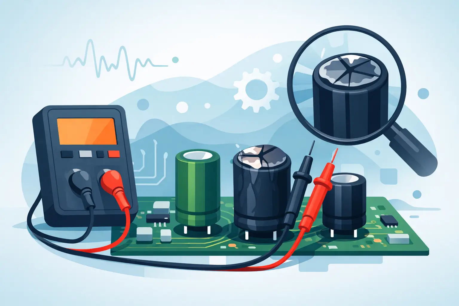
A capacitor can measure close to its rated capacitance and still be the reason a power supply oscillates, a control board resets, or an audio circuit develops noise. An ESR meter identifies this failure mode by measuring equivalent series resistance, the small resistive loss present inside every real capacitor. When that loss rises beyond an acceptable level, the capacitor may no longer filter ripple current or deliver transient current effectively.
For PCB repair, production troubleshooting, and incoming inspection, ESR measurement is often faster than removing a suspect capacitor and checking capacitance alone. The reading must still be interpreted in context: capacitor type, value, voltage rating, temperature, test frequency, and circuit connections all affect the result.
What an ESR Meter Actually Measures
An ideal capacitor has only capacitance. A physical capacitor also has resistance from its foil, electrolyte, terminals, internal connections, and dielectric losses. Equivalent series resistance, or ESR, represents those losses as a resistance in series with the capacitor.
At low ESR, a capacitor can pass ripple current with limited heat generation and maintain its filtering performance. At high ESR, ripple current produces more voltage drop and internal heating. In switching regulators, this can increase output ripple, destabilize a feedback loop, or cause intermittent startup faults. In older linear power supplies, high ESR electrolytics can lead to hum, poor regulation, and reduced load capability.
An ESR meter applies a small AC test signal and calculates the resistive portion of the component’s impedance. This is different from a DC resistance measurement. A digital multimeter’s ohms range is useful for finding a shorted capacitor or observing a basic charging response, but it does not provide a valid ESR value.
Capacitance and ESR should be treated as complementary measurements. A capacitor can lose capacitance, develop high ESR, become leaky, or fail short. No single test catches every condition.
Why Test Frequency Changes the Reading
ESR is frequency-dependent. Capacitors used in switching power supplies are often specified at frequencies such as 100 kHz, because that operating range better reflects the currents they handle. A measurement made at a much lower frequency can be useful, but it may not correlate closely with the manufacturer’s impedance or ESR specification.
This is why test frequency is a practical selection criterion, not a brochure detail. A meter operating at 100 kHz such as LCR-Reader line of devices is generally well suited to evaluating low-ESR capacitors in switching circuits. Higher-frequency measurement capability can provide additional visibility when testing modern compact components and investigating behavior closer to their operating conditions.
Frequency is not the only variable. Temperature matters as well. Electrolytic capacitor ESR usually rises substantially at low temperature, while a part tested immediately after power has been removed may read differently from the same part at room temperature. Compare readings under similar conditions whenever repeatability matters.
Reading ESR Values Without Chasing One Universal Limit
There is no universal pass/fail ESR number for all capacitors. A 1,000 µF low-ESR polymer capacitor may be expected to measure only a few milliohms, while a small general-purpose electrolytic capacitor may normally measure several ohms. Judging both against the same threshold produces false failures and missed defects.
Start with the component’s datasheet when it is available. Look for impedance, dissipation factor, or ESR specified at a stated frequency and temperature. If the installed part is from an unknown source, compare it with a known-good board, an identical replacement part, or a component from the same circuit position.
The most useful field diagnosis is often comparative. If several output capacitors on a supply rail are identical and one reads materially higher than the others, it deserves attention even when its capacitance appears acceptable. Likewise, an ESR value that changes significantly after gently flexing a lead or touching a connection may point to a poor solder joint rather than a failed capacitor.
Be cautious with very low values. Lead resistance, probe contact resistance, oxide on terminals, and measurement fixture quality can dominate a milliohm-level reading. Zeroing or compensating the probes before measurement is essential when the instrument supports it.
In-Circuit ESR Testing: Fast, but Not Automatic
In-circuit testing is one of the main reasons technicians use an ESR meter. It can reduce disassembly time and quickly narrow a fault to a group of capacitors. However, the circuit around the capacitor can influence the result.
Parallel capacitors lower the apparent ESR. Inductors, transformers, low-resistance semiconductor paths, and other connected components can create alternate paths for the test signal. A low in-circuit ESR reading does not always prove that the selected capacitor is healthy. A high reading is often more actionable, provided the probes have solid contact and the board is unpowered.
Before probing, disconnect all power sources and discharge the capacitor safely. Do not assume a board is discharged because its indicator LED is off. High-voltage capacitors in offline power supplies require controlled discharge procedures and suitable safety practices.
For ambiguous readings, isolate one lead or remove the part. This takes longer, but it separates the capacitor from parallel circuitry and provides a defensible measurement. In production or quality-control work, the same principle applies: define whether the inspection process is measuring the individual component or the assembled circuit behavior.
What to Look for in an ESR Meter
An ESR meter should be selected for the components and failure modes you actually encounter. Basic accuracy matters because a small difference in ESR can distinguish a normal low-loss capacitor from a marginal part. Resolution also matters, especially for low-ESR aluminum electrolytic and polymer capacitors used on modern power rails.
For board-level work, probe geometry is equally important. Conventional clip leads can be slow on dense PCBs and may contact adjacent pads or components. Fine probes, Kelvin-style connections where appropriate, and tweezer-form instruments improve access to small surface-mount capacitors and reduce handling time.
Consider these operating requirements together:
- Test frequency appropriate for switching-power and general electronics work
- ESR range and resolution that cover milliohm through multi-ohm measurements
- Stable probe compensation and low-resistance contact capability
- Clear indication of measurement mode, range, and battery condition
- Calibration support when measurements affect service records, quality documentation, or customer acceptance
A combined handheld LCR instrument can be more efficient than a dedicated ESR-only device when troubleshooting includes capacitance, inductance, resistance, and component identification. The trade-off is workflow: a dedicated ESR function may be the quickest path when capacitor faults are the primary concern, while an LCR meter provides broader diagnostic coverage on mixed-component assemblies.
Professional instruments such as Siborg’s handheld LCR and Smart Tweezers configurations are designed around direct component access, with test-frequency options, compact probing, and calibration-supported measurement for PCB work.
A Repeatable ESR Test Procedure
A reliable result begins before the probes touch the board. Confirm the equipment is off, disconnect battery packs or external supplies, and discharge stored energy. Inspect the capacitor and surrounding area for leakage, venting, lifted pads, heat discoloration, or damaged solder joints. Visual damage is not required for ESR failure, but it can direct the investigation.
Set the correct ESR or LCR measurement mode, select the intended test frequency if the instrument allows it, and compensate the probes according to the meter’s procedure. Keep probe pressure consistent. On small SMD capacitors, contact resistance can change dramatically if one tip lands on solder mask, a contaminated pad, or the edge of a termination.
Record the measured value, the capacitor’s marked value and type, the test frequency, and whether the part was measured in circuit. This record turns a one-time reading into useful diagnostic data. It also makes recurring failures easier to identify across repair lots or production boards.
When a reading is questionable, compare it with a known-good reference before replacing parts. Replacing every capacitor that looks old is sometimes justified in aging equipment, but it is not a substitute for measurement. A targeted ESR test reduces unnecessary rework and helps preserve original components that remain within specification.
Common Misinterpretations to Avoid
A low ESR reading is not always good. A capacitor that has failed short may show very low resistance or may be masked by a parallel path on the board. Check for abnormal DC resistance, excessive current draw, and rail-to-ground shorts where appropriate.
A high reading is not always a failed capacitor. Poor probe contact, corroded terminals, cracked solder joints, and insufficient probe compensation can all add apparent resistance. Confirm the connection before condemning the component.
Finally, do not compare an ESR reading taken at one frequency with a datasheet value specified at another frequency without qualification. The measurement may still reveal a relative fault, but it is not a direct specification comparison.
The best use of an ESR meter is not to treat one displayed number as a verdict. Use it to make a fast, controlled comparison between the capacitor, its specification, its circuit role, and a known-good reference. That approach turns a compact measurement into a practical decision about what to repair next.